Feature-Based Design of Building Forms Using an Improved CSG Tree
Fang Weidong*, Tang Ming Xi,
Liu Xiyu*
Design
Technology Research Centre, School of Design
The Hong
Kong Polytechnic University, Hong Kong
*DTRC and
Department of Computer Science
Shandong
Normal University, Jinan, China
Abstract
Evolutionary technologies can be effectively used for architectural
design supporting innovation, optimisation and planning. In this paper, we introduce
a method of generating building forms using an improved Constructive Solid
Geometry (CSG) tree. In this method, an abstract building form is represented
by the makeup of its main body and its exterior features. Traditional CSG tree
is modified for the representation of diversity building forms. In this paper,
this method is described with the presentation of the preliminary results of
the implemented system.
1.
Introduction
From the perspective of computing, an architecture form can be viewed as
a combination of many distinctive features related to the environment. To
formally define the style of a building in a CAD process is difficult. However,
it is easier to work at a level of abstraction of building style in terms of
geometric features. In [2], for example, the style of a building is interpreted
using hierarchical levels with syntactic and semantic mapping from concept to
form. Semantics are derived from the forms and result in important decisions in
the design process. In this paper, we represent the style of a building using
features from which different build forms are generated.
Feature-based design has a long history originating from the engineering
domain, where the gap between design and manufacturing must be bridged. In such
a domain, features are meaningful elements for designers and the use of them
can speed up the design process as well as provide a means for standardisation,
thus reducing the cost and time to market. Generally, a feature is considered
as:
w
a specific geometric configuration formed on a surface, edge or corner
of a work piece [3],
w
distinctive or characteristic part of a work piece, defining a
geometrical shape, which is either specific for a machining process or can be
used for configuration and/or measuring purposes [4], or
w
a generic shape which carries some engineering meaning [5].
In our method, we express the style of a building with the
characteristics of its main body construction and exterior elements. The main
body of a building can be obtained using 3D modelling method. The exterior
building elements, such as roof, wall, window, gate, and so on, are represented
as compound features. In light of this, the generation of a building consists
of two steps: (1) generating the main body with a 3D modelling method, and (2)
adding building elements to the main body (fig 1).
Fig 1 Steps to generate a
building
In the following text, we give a brief review on solid modelling
representations in section 2. In section 3, we introduce our improvements on
traditional CSG tree to meet the requirements of generating diversified
building forms. Section 4 introduces our idea to represent building elements
with feature technology. Section 5 presents the preliminary implementation of
the proposed method. Finally, we conclude this paper in section 6.
2. Solid
modelling representations
Solid modelling is a rapidly growing area of research and development in
the CAD domain. As a field, solid modelling spans several disciplines,
including mathematics, computer science, and engineering. Three major
representation schemes used in generative design are spatial partitioning,
boundary representations (B-rep), and constructive solid geometry (CSG).
In spatial-partitioning representations, a solid is decomposed into a
collection of adjoining, non-intersecting cells that are more primitive than
the original solid. The most common spatial partitioning representation schemes
include cell decomposition, spatial occupancy enumeration and cctrees. In cell
decomposition, each cell decomposition system defines a set of primitive cells
that are typically parameterised. Cell decomposition is not necessarily unique.
Spatial occupancy enumeration (also called exhaustive enumeration) is a special
case of cell decomposition in which the solid is decomposed into identical
cells arranged in a fixed and regular grid. These cells are often called
voxels. Octree is a hierarchical variant of spatial occupancy enumeration. The
essential property of octrees is that they record the shape information of an
object in a spatially ordered manner, and the highly hierarchical nature of
them suggests the use of divide-and-conquer recursive paradigms.
The boundary representation, or B-rep, represents solids in terms of
bounding surfaces, with a convention to indicate which side of boundary is
inside. It is based on complete topological information as well as geometry.
Topology (fig 2) provides mathematical basis for complete definition of
well-formed solid. A solid object is represented by a complicated data
structure giving information about each of the object's faces, edges and
vertices and how they are joined together. With B-bep, the description of the
object can be into two parts: topology records the connectivity of the faces,
edges and vertices by means of pointers in the data structure, and geometry
describes the exact shape and position of each of the edges, faces and
vertices.
Fig 2 Topology of boundary
representation
In CSG, a solid is represented as a combination of primitives, or
building blocks. Typical primitives include rectangular blocks, cones,
cylinders, spheres, tori and prisms. Primitives are first scaled based on
specified dimensions, then moved by a rigid motion, or a combination of
translations and rotations, and finally merged together by regularised Boolean
operations. There are three typical Boolean set operations: union, intersection
and subtraction. Because the final geometry changes depending on the order of
the operations performed, the order of operations can be stored in a binary
tree structure, which is called a CSG tree. Fig 3 gives an example of using CSG
tree to represent the design process of a mechanical part.
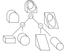
Fig 3 A CSG tree example
In reference to generative architectural form design, various methods
have been explored to generate novel building envelopes. A number of computer
models are used to simulate the development of prototypical forms that are then
evaluated on the basis of their performance in a simulated environment. In [7],
optimisation functions are integrated with the form generating processes in
order to generate new forms responding to varied design environments to be
created and determined through a series of complex mathematic transformations.
3. The
Improved CSG Tree
Among the three solid modelling representation methods mentioned in
section 2, CSG tree is highly recommended in generative design systems because
of its conciseness and easiness for genetic encoding. But the primitive numbers
and Boolean operations in a traditional CSG tree severely impair its ability in
generating diversified building forms. To address this issue, we improve the
traditional CSG tree in two aspects: primitive representation and operation
set.
3.1 Uniform
representation of CSG primitives
Most CSG modelling systems provide just a few standard primitive shapes
of a unit size, whose position, and orientation are initially set within the
primitive's local coordinate system. The designer chooses appropriate
primitives, then sizes, positions, and combines them to form complex shapes. A
primitive's size, shape, position, and orientation are controlled by specifying
the values for a small set of variables. For example, rectangular solids, or
blocks, are almost always available in a CSG system. A particular instance of a
block is produced by specifying its length, width, height, and subsequently its
location and orientation within a world coordinate system. In our method, we do
not intend to provide a specific number of primitives. Instead, we propose a
uniform representation for a wide range of primitives.
Definition 1 A primitive is
represented by a modelling method, two curves and four parameters, which can be
expressed as:
Primitive = (m, draft, step,
twist, portion, c1, c2)
Where
-
m is a creation method such as
sweeping, revolving or lofting,
-
c1 and c2 are two curves,
-
draft represents the
angle with which the swept profile is to draft out (positive) or in (negative)
while sweeping,
-
step converts a
circular sweep path into the specified number of linear segments. The results
are polygons, and the intent is to create simpler geometry by keeping faces
planar. The default is 0. This option may only be used when specifying the path
as a position and axis of revolution,
-
portion specifies the angle
to sweep around another, given in radians. The default is 2π,
-
twist represents how
much the profile twists in total as the profile is swepting along the path,
regardless of the length of the path.
In the above definition, a primitive solid can be created with three
methods: sweeping a curve along another, revolving one around another or
lofting one to another. Four parameters specify how the solid will be created
in more details.
Definition 2 A curve is defined
by a type, a flag indicating whether the curve is closed, and a collection of
control points, such that
Curve = (t, f, p1,
p2, ..., pn)
Where
-
t: the curve type, which can be
line, arc or spline,
-
f: flag indicating whether this
curve is closed,
-
Pi, i = 0, 1, …, n:
pairs of float numbers, representing the coordinates of control points,
Note that different curve types need different numbers of parameters,
and the flag is not always necessary. For example, a straight line needs two
control points; an arc needs three points and a line strip or a spline usually
needs variable number of points.
When generating a primitive solid, if the method of a primitive is
sweeping, the resulting solid will be created by sweeping curve c1 along curve
c2. In this case, c1 should be a closed curve, while c2 can be either an open
curve, e.g. a line, or a closed curve. If the method is lofting, then both c1
and c2 should be closed curves.
Some modelling tools support an even more complex sweeping method called
Variable Section Sweep (VSS). A VSS allows for the creation of some very
complex geometry by controlling how the section will change along the
trajectory for the feature. For example, in ACIS, a law provides symbolic
representations of equations that are parsed in much the same way that
equations are. A law is represented internally by a tree of C++ classes that
know their dimensions, how to evaluate themselves, and how to take their exact
(symbolic) derivatives with respect to any combination of variables. In
addition, law utility functions numerically integrate, differentiate, and find
roots. Such a method usually uses mathematical functions to control the
changing of a section. It’s too complex to be applied in the generative design
process.
It is obvious that all primitives in the existing CSG methods (say,
block, cone, wedge, cylinder, torous, etc.) can be represented by this uniform
method.
3.2 Extended
CSG operation set
CSG is a method for describing the geometry of complex models by
applying set operations to primitive objects. Traditionally a CSG tree contains
two kinds of operations, i.e. rigid Boolean operations and transforming
operations. However, a feature based generative design system should be
flexible so that the generation process can not only add new instances of
feature primitives to the model, but also can modify various aspects of the
existing features.
In our method, operations involved in the improved CSG tree include
three categories of operations: Boolean operations, transformations and feature
operations. We list the operations of each category as follows.
1)
Boolean operations
w
Union,
w
Intersection,
w
substraction.
2)
Transformations
w
Translating,
w
Rotating,
w
Scaling.
3)
Feature operations
w
Creation,
w
Deletion,
w
Modification.
By providing a uniform expression of primitives and extending the
operation set, our improved CSG tree can now generate a much wider range of
building forms than that of a traditional one. In light of the above
description, now we give the formal definition of our improved CSG tree.
Definition 3 An improved CSG
tree recursively expressed in Backus-Naur Form as:
CSG tree ::= <CSG tree> < Op> <CSG
tree> | <CSG tree>
|
<Transformation> | <Primitive Solid>
Op ::= Boolean operation | Transformations | Feature
operation
Boolean operations ::= Union | Intersection |
Substraction
Transformation ::= Translation | Rotation | Scaling
Feature operation ::= Creation | Deletion |
Modification
Primitive ::= <Method><Curve><Curve>
Method ::= Sweeping | Revolving | Lofting
4.
Representing building elements with features
Many different kinds of features have been proposed in the development
of CAD systems, such as functional features, assembly features, mating
features, physical features and even abstract features. All of these features
have to be associated with the basic shapes to which they are attached. Shah
defined the requirements a feature should at least meet [6]: a physical
constituent of a part, to be mapped onto a generic shape, engineering
significance and predictable properties.
To represent building elements, it is important to give a feature
taxonomy to classify all features in a structured way. By doing this, we can
also define features with the notion of inheritance, i.e. properties of super
classes can be inherited by subclasses without explicitly being repeated.
In our method, we adopt the feature taxonomy scheme presented by Wilson
and Pratt based on the overall shape of features and the assumption that
features will be incorporated in solid modelling systems [8]. Wilson and Pratt
distinguish explicit and implicit feature taxonomies which are related to form
feature representation. Fig 5 illustrates this taxonomy.
Fig 5 the taxonomy proposed by
Wilson and Pratt
According to this taxonomy, features can be represented either
implicitly or explicitly. In the explicit representation all geometric details
of a feature are fully defined. In the implicit representation, sufficient
information is supplied to define the feature, but the full geometric details
have to be calculated when required. A cylindrical window for example may be
defined implicitly in terms of its radius and depth or explicitly in terms of
the set of faces which compose it in a boundary representation model.
In our implemented system, we represent the building elements, e.g.
roof, door, window, podium, column, and so on, as compound features. A compound
feature is defined as a group of sibling primitive features. It is useful to
treat some features as a single entity because for example they might perform a
single function or may be machined by the same manufacturing procedure. The
members of a compound feature are treated internally as primitive features with
relationships, but externally a number of most commonly used compound features
are defined, so that designers can generate instances by simply supplying the
parameters. Choices are also given for creating new compound features by
defining the relationships between the existing primitive features.
It should be stated that in addition to building elements, special
modelling techniques for the design of building forms are also considered in
our method. Most of these techniques are related to the construction of the
main body of buildings. We view these techniques as special features and
represent them explicitly in the form of our improved CSG tree.
5.
Implementation
Present feature based CAD systems generally do not offer a facility to
easily define one's own features. Feature definition usually consists of some
kind of programming interface to the geometry modeller. In Knowledge Based
Engineering (KBE) systems, the programming interface as well as the access to
the geometry modeller is better when compared with "traditional" CAD
systems. Nevertheless, even within KBE systems, feature definition is difficult
and error prone, requiring extensive programming skills as well.
We employ the so-called Object Oriented Technology to develop our
software system. Features are viewed as design objects, belonging to some
general class, inheriting properties from their parent classes. A single
feature is defined in terms of the feature name or ID code, the feature class,
profile type, faces, parameters, a list of relationships and the feature
location and orientation. Each face of a feature is described by the face name
or ID code, the face type, face shape type, the face normal, its parent face
and surface finish. The parametric representation of features provides a
powerful way to change features with respect to their dimensions.
Fig 6 shows some preliminary results generated by the software system.

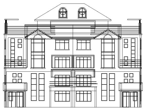
Fig 6 Some
results generated by the proposed method
6.
Conclusions
This paper presents a new idea of generating building forms using an
improved Constructive Solid Geometry (CSG) tree. The traditional CSG tree is
improved with a uniform representation of primitives and an extended operation
set.
Future work of this research will be concentrated on applying domain
knowledge to the generation of architectural forms. The generative design of
building groups using co-evolutionary technologies is also a direction of our
future endeavour.
References
[1] Tang M. X., Frazer, J. H., “An Artificial Intelligence Approach to
Industrial Design Support”, Generative Art, 1998, Milan, Italy, December, 1998.
[2] Gero, J. S. and Ding, L. (1997). Exploring style emergence in
architectural designs, in Y-T. Liu, J-H. Tsou and J-H. Hou (eds), CAADRIA'97,
Hu's Publisher, Taipei, Taiwan, pp. 287-296.
[3] CAM-I's illustrated glossary of workpiece form features,
R-80-PPP-02.1, 1981.
[4] Erve A.H. van't, Computer Aided Process Planning for Part
Manufacturing, an expert system approach, PhD thesis, University of Twente,
1988.
[5] Wingerd L., Introducing form features in product models, a step
towards cadcam with engineering terminology, Licenciate Thesis, Dept. of
Manufacturing Systems, Royal Institute of Technology, Stockholm, 1991.
[6] Shah J.J., Philosophical development of form feature concept, CAM-I
report P-90-PM-02 , 1990, 55-70.
[7] Liu X. Y., Frazer, J.H., Tang M. X., “A Generative Design System
Based on Evolutionary and Mathematical Functions”, Generative Art 2002, Milan,
Italy, December, 2002.
[8] Wilson P.R., Pratt M.J., A taxonomy of form features for solid
modeling, in Geometric Modeling for CAD applications, eds. Wozny M.J.,
McLaughlin H.W., Elsevier Science Publishers B.V. (North Holland), IFIP., 1988,
125-135.