Anamorphic Perspective & Illusory Architecture
Dr. Tomás García Salgado, BSArch,
MSArch, PhD, UNAMprize, SNIm.
Faculty of Architecture, National Autonomus University
of México.
Abstract
|
A |
namorphic perspective can be sometimes quite paradoxical. This is the case with the famous false vault by Andrea Pozzo at Saint Ignatius in Rome. Pozzo himself did not consider this painting as an anamorphic projection, but it is indeed. Pozzo deduced the correct perspective drawing for the large canvas (intelaiautura), but what the observer sees is quite different. This article is divided into three parts that can be read separately depending upon the reader’s interest. The first part gives us an historical review through some treatises related to the subject and some famous masterpieces. The second part deals with the principles that govern anamorphic perspective, considering the basic cases of projection. One of these cases is presented in detail in this part. Finally, the third part is devoted to the analysis of the vaults of Sant’Ignazio and Collegio Romano by means of the author’s method, termed Modular Perspective. For a better understanding of the origin of Saint Ignatius’s vault, we include a brief historical background in order to grasp the idea that Pozzo’s painting is fundamentally an architectural solution instead of a purely pictorial exercise.
1. Historical Background
It is quite common to encounter the theme of anamorphic perspective in the standard literature for all types of applications, from portraits to murals and scenography, to architecture itself. Yet curiously it would appear that the praxis of anamorphic perspective is reserved to its creators alone, its popularity being overshadowed by linear perspective. We will review some brief historical examples as a way to dig into the theme, extracting consistent principles in the execution of this singular application of perspective [1].
The first treatment in a detailed study on the perspective appearance of a sphere may be De Prospetiva Pingendi by de Piero della Francesca (1482) for the work Virgin with Child, Saints, and Angels (1474). When one appreciates the original work from the vantagepoint, what stands out is the intriguing shape of the ovaloid hung from the decorative shell over the altar niche. One would expect the artist to have chosen a perfect sphere, more in line with the symmetry of the pictoral theme. Yet if we come closer toward the center of the painting, keeping the view at the same height while turning the angle of view obliquely, the ovaloid becomes a perfect sphere.
Figure 1 suggests the
proper viewing angle. We deduced from this drawing that central deformation of
the ovaloid generates a viewpoint different from that projected from the rest
of the painting. This may be the first painting that superimposes an anamorphic
projection onto a linear projection.
In the 1533 painting The Ambassadors by Hans Holbein, a “painting” may be seen lying on the floor between two persons. Its extreme deformation makes it barely recognizable, but a nearly edge-on view of the work from above reveals a skull in the direction of the odd “painting.”
Erhard Schön’s work Three Kings and a Pope (1535) explored the representation of a portrait hidden among landscapes, an idea he also applied to the discreet illustration of obscene scenes in anamorphic perspective.
In 1567, Baldassare Lanci designed a instrument to obtain perspectives with a visual field opening of 180°. The instrument was made of a circular bronze platter placed horizontally upon a tripod which adjusted the height. Semi-cylindrical paper was wound around its edge. A tubular eyepiece was placed in the middle with a retractable metallic stylus underneath. The eyepiece was high enough to overlook the semicircle of paper and sight points of interest while the retractable metallic stylus drew on the paper. Egnazio Danti, in his edition of Vignola Due regole della prospettiva pratica (Rome, 1583), presented a profile portrait drawing deformed at a ratio of 4:1; an idea Marolois would replicate years later.
Salomon de Caus, in his treatise La Perspective, avec la raison des ombres et miroirs (London, 1612), studied the appearance of uniformly-sized inscriptions on a vertical wall, whose strokes are closely related to the concept of distance. His preface notes, “Of all mathematics, Perspective alone is pleasing to the eye” – giving us courage to press on. Samuel Marolois followed up on Danti’s erroneous methodology in his attempt at canine anamorphic profile (1614) drawn at the same 4:1 ratio —without considering any specific viewpoint. He also studied the problem to be able to draw on surfaces in corners. Johann Heinrich Glaser portrayed the Biblical scene of Adam and Eve’s Fall from Grace (1638). What appears as a lake in the landscape resolves into the face of Christ with his crown of thorns when viewed from the extreme right of the engraving.
Jean-François Nicéron executed an anamorphic mural of Saint John in Patmos in Rome’s SS. Trinità dei Monti monastery, which he also illustrated in La Perspective curieuse ou Magie artificiele des effets merveilleux (1646 edition). He also researched anamorphic projections onto conical and cylindrical surfaces. Abraham Bosse, a disciple of G. Desargues, studied the procedure to transfer a flat projection onto a cylindrical vault by means of a net of “visual” threads, as illustrated in his work Moyen universel de pratiquer la perspective sur les Tableaux, ou Surfaces Irregulieres (Paris, 1653). Grégoire Huret, in his work Optique de Portraicture et peinture, en deux parties (Paris, 1670), explored the concept of the anamorphic portrait on architectural elements such as walls and vaults (planche VI).
Samuel Van Hoogstraten painted different anamorphic views of a German house inside a wooden box (58 x 88 x 63.5 centimeters, c.1650), which, when seen through tiny holes at the ends of the trick box, produce a vivid three-dimensional effect. Andrea Pozzo, in his ceiling of Sant’Ignazio (Rome, 1691-94), applied an interesting image transfer procedure – on a massive scale – of a flat plane onto a hemi-cylindrical plane, achieving a spectacular trompe l’œil effect. He outlined this procedure in the treatise Perspectiva, Pictorum et Architectorum (Rome, 1693).
Bernard Lamy, author of tracts on many matters, also takes up the procedure to transfer an image onto another in a spherical anamorphic projection, exemplified in an engraving of his Traité de Perspective… (Paris, 1701). Johann Jacob Schübler presents a must suggestive engraving in his treatise Perspectiva… (Nuremberg, 1719-20); it looks very distorted when observed in a conventional manner, but when the eye is placed almost side-on at the drawing’s “o” the three arches in the foreground take on their correct proportions, as do those that recede into the distance. Christoff Rudolf (1553), Georg Galgemayr (1614), Daniel Schwenter (1618), and George H. Werner (1796) attempted to resolve the age old problem —studied by the Greeks around 400 B.C.— of proportioning same-sized lettering on tall columns and walls, which for the purposes of our study corresponds to the problem of anamorphic projection onto a curved virtual plane.
Adèle Le Breton, in her Traité de perspective simplifiée (linéaire) (Paris, 1828), brings a certain black humor to the application of anamorphic perspective in self-portraiture. Le Breton also worked on the instrumentation used for drawing panoramic vistas. La Gournerie studied geometral distortion of architectural plans in Traité de perspective linéaire (1859), demonstrating how three architectural plans in conformal projection correspond to an identical perspective result. This was achieved by shifting the observer’s symmetrical sight line laterally while warping the plans in the same direction.
The famous Ames Room consisted of placing the observer at an oblique position relative a room with trapezoidal walls and floor but gave the appearance of an ordinary room, right down to the checkered floor. People who were inside seemed to have differing heights; while one had to bend down to fit into the room the other appeared to loose half of his or her height. This interesting experiment combined anamorphic perspective with accelerated perspective. Blanche Ames (sister to Adelbert) explored the effect of retinal image in painting [2]. In his work Virtual America IV, Daniel L. Collins introduced distinct points of observation to read a series of images in anamorphic projection on panel screens in corners, curiously presented in the Marolois style [3].
The author’s essay on cenacolo Vinciano [4] demonstrated how the geometry of the illusory refectory may correspond to innumerable architectural plans by reconstructing its perspective under the principle of anamorphic central perspective. This principle consists of maintaining the diagonal vanishing point for the room’s floor steady, such that every enlargement of a room’s depth correlates to an increase in the distance of observation, and vice versa. Our hypothesis is that Leonardo da Vinci constructed perspective at a distance of 4.43 meters, from which the distortions on the edges of the figures on the side of the table are corrected. The farther away one is, the more robust the figures appear. Contradictory, isn’t it? You expect just the reverse, that is, the closer you are, the more distorted it is.
Despite the abundance of illustrative materials on anamorphic perspective, relatively little has been dedicated its theoretical bases or its relationship with linear perspective [5] to establish whether anamorphic projection is a unique case of linear perspective or an independent projection. Similarly, in this context study must be made of curvilinear anamorphic projection, accelerated perspective, and what the author terms as “anti-perspective.” This line of questioning clearly leads us to deliberate on a general theory of perspective that encompass all classes of projection. While it would be interesting to outline some concepts in this regard, this contribution will confine itself to studying the principles governing anamorphic perspective.
2. Principles and Examples of Anamorphic Perspective
There is a tight relationship between the lateral distortion of an image produced by linear perspective when the eye moves toward the edges of the perspective plane and the distortion resulting from the transfer of the image onto a second plane. Although lateral distortions are sometimes considered to be anamorphic projections, a rigorous analysis does not accept such an explanation because the perspective elongation produced by increasing the angle of the visual field is in the same plane as the image. A true anamorphic projection is created when the image in the perspective plane is transferred onto a second plane. This transfer may be from flat or curved plane onto another flat or curved one, that is, any combination of the two. This principled distinction between lateral distortion and anamorphic projection does not pose a necessary condition for image transfer in each and every case.
These four the concepts will serve us to get through the balance of the exposition.
1. The perspective plane (PPL) is that containing the image the observer should perceive, whether in a real or a virtual plane. Thus, the image may either be contained in or projected onto the PPL.
2. The observer visual of symmetry (VS) is always perpendicular to the PPL. The VS will also be referred to as the “observer’s sight line.”
3. The anamorphic plane (AnPl) may or may not coincide with the PPL, but it will always contain the distorted image.
4. The pictorial plane (pPl) is that containing the artistic image (painting or drawing), which may or may not coincide with the PPL or AnPl.
Central Anamorphic Perspective
When the PPL and the AnPl are straight planes and occupy the same position (according to concep 3), a projection is produced that here we shall term central anamorphic perspective. This case adheres in real and fictitious spaces when the depth of the space is adjusted as a function of the distance of observation for the purpose of increasing or reducing the depth of the perspective effect or, similarly, starting from a pre-established effect to calculate the distance of observation.
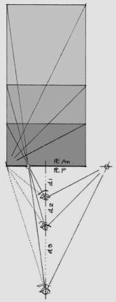
Figure
2a presents three spaces of differing
depths (d1, d2, and d3) where the
perspective result is identical, as in Figure 2b.
It is notable that increases in distance d are in direct function of the increase in the depth of thespace. This is the most difficult case to perceive at a casual view, as in cenacolo Vinciano, because the distortion is only created in depth, that is, it is not foreshortened to make it notable. A corollary to this projection would be when the geometry of the PPLs and AnPls is different, even when one is in the same position relative the without variation to distance d. We find an example of this in Abraham Bosse’s famous engraving (Moyen universel de pratiquer la perspective, Plate 88) with an illustration captioned “How to draw the perspective grid on a cylindrical vault.”
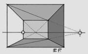
Lateral Foreshortening
As its name indicates, lateral foreshortening occurs when the image exceeds the limits of the visual field, particularly in angles of observation greater than 75°.
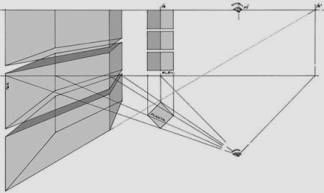
Figure 3 illustrates lateral distortion of the image, which is best observed at a distance of four centimeters in the direction of the vanishing point (pf). Note here how the extreme distortion tends to disappear or correct itself. A deceptive variation on lateral foreshortening is found when an object fills half, or nearly half, of the open visual field, obliging the observer to rotate the view to fix the image in the center of the PPL, as happens in the finta cupola of Saint Ignatius. Another illusory variation is produced when foreshortening of the body under observation generates an asymmetrical vanishing point (pfa) in a location that can be confused with the PPL’s vanishing point (pf), as shown in Figure 4.
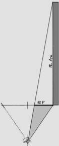
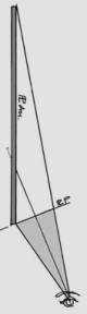
Anamorphic Perspective on a Flat Plane
Figure 5 shows how greatly distorted or oblique distortions are produced when the image from the PPL is transferred onto a flat or orthogonal plane, as in the celebrated mural of Saint John in Patmos by François Niceròn. As this work exemplifies, it is the selfsame oblique angle of the AnPl that places limits on the opening of the PPL visual field. In practice it is preferable to restrict the angle of the visual field to permit the VS to be directed toward the center of the image (or pictoral motif), necessitating a slight twist to the PPL, as shown in Figure 6.
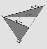
Anamorphic Perspective on an Oblique Plane
This next case is more closely related to the practice of Modular
Perspective than to traditional methods, insofar as there is little distortion
in the image transfer and the relationship between perspective and anamorphic
planes is bound by the visual field. Maintaining a fixed observation point (O), the PPL is rotated, thus generating a new plane
which we shall term the anamorphic plane (AnPl). The rotation of the AnPl may neither reach point O nor terminate in a co-plane with the limit to the
visual field. The image resulting from any rotation to the AnPl must be
observable from O, such that its
perception in the anamorphic and perspective planes must be identical. As may be inferred from Figure 7, the size of the AnPl will necessarily be different from
the PPL’s size – greater or lesser depending on the direction of
rotation.
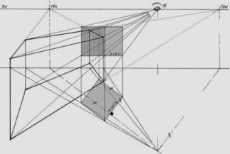
The following is a list of the steps in the process of constructing an AnPl greater than the PPL. Please refer to Figures 8a and 8b.
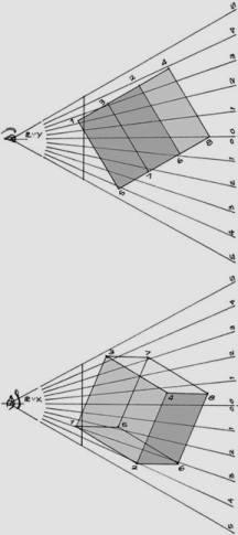
Take cube 1, 2, 3… 8, represented in the symmetry planes of visual rays X/Y (PLvx /PLvy) in Figure 8a. To correctly interpret the procedure, we will require the concept of symmetry planes of visual rays, which in essence is not a new concept. Alberti (1436) and Leonardo (1492) implicitly suggested it when they geometrically formulated human vision as a visual pyramid, albeit they did not systematize their measurement. The advantage of these planes is the ability to obtain a quick, direct reading of the projective coordinates Xo/Yo, provided the observer’s visual rays that intersect the cube are constant in both planes. Very well. A conventional reading of coordinates X, Y, P from any corner on the cube implies deducing them from a distorted plans, which requires use of special scales that are only useful each time the AnPl is rotated.
1. To generate the AnPl, the PPL is rotated on any of its outer points, exactly as shown in Figure 8b.
Figure 8a
2. (beginning
from/starting from/based on) the PPL modulation, visuals are traced from point O
until they intersect the AnPl, thereby defining its horizontal modulation. This
modulation is different from vertical modulation in geometric construction.
3. The vertical modulation of the AnPl’s enlarged side is equivalent to the breadth of the visual field as measured in the depth obtained from the horizontal rotation.
4, The front view of the AnPl is determined. This plane is called a conformal projection of the PPL, once the geometric coherence of the distorted checkerboard is verified through its diagonals.
5. To obtain the anamorphic perspective of the cube, it is sufficient to transfer the projected Xo/ Yo coordinates onto the PLvx /PLvy and the AnPl.
6. To appreciate the image on the AnPl, the image must be placed obliquely before the observer at the angle of rotation indicated in Figure 8b.
Anamorphic Perspective onto a Virtual Plane
In most anamorphic perspectives the distorted image resides in the pPl, which stimulates coherent perception of a PPL image and necessarily transforms it into a virtual plane. Yet paradoxically, what we see when we look laterally at a coherent image contained in a PPL is its projection into a virtual AnPl. This is difficult to comprehend precisely because it is such a commonplace event —and even more so when objects familiar to the observer are concerned. Once the image is identified, few search out the true perspective or illusory effect.
The problem of anamorphic perspective onto a virtual plane may be posed in two different directions: (a) Generating the image in the PPL and transferring it to the AnPl, or (b) Vice versa, that is, generating the pictoral image in the AnPl to find it in the PPL. The latter appears to be a contradiction, but it is not. It is precisely the case of the Sant’Ignazio and Collegio Romano vaults we turn to in the next section.
3. Le Finte Cupole di Sant’Ignazio and the Collegio
Romano
Pozzo: pittore, prospettico e architetto
Architecture is the central theme to the works by Brother Andrea Pozzo, elaborated sculpturally in some instances, as we can infer from his description of the great Teatro delle Nozze di Cana, “Dalle preparazione antecedenti si è cavata questa nobile Architettura.” [6] The term cavata clearly refers to the perspective construction of the architecture by means of the pianta in iscorcio (foreshortened plan) and the profilo in prospettiva (perspective section), yet it also evokes the idea of “sculpting” the forms in the drawing. The theater’s machina in this work is composed of six telari (canvases), not counting those that were to go in the middle of the main arch to simulate nothing less than immense clouds of angels. The effect must have been unique, impossible to reconstruct today because once the celebration was over there was no place to save it. The fate of this machine and many others was to be ephemeral, albeit transcendental [7].
In the Marriage of Cana, Pozzo originated a monumental architecture, sacrificing the utility of the space to the sole purpose of calling the event. Observe how the mysterious upper chambers on both sides of the central arch in this work, shown in Figure 9, open their lunets onto a view of the main patio to permit a view of Jesus converting water into wine [8].
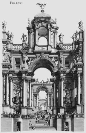
This quality of conceiving a scene as an architect while executing it as a perspectivist features prominently in Pozzo’s work, “É Pittore; Dunque non sará buon Architetto; ma più tosto inferite il contrario. É buon Pittore, e buon Prospettico, dunque sarà buon’Architetto.” [9]
If Ghirlandaio took liberties with place and people in his pictorical narrative [10], Pozzo took similar freedom with space and time, taking his narrative to a continual experimentation of space and architectural forms, creating a play of solids and transparencies, of inside and outside, of arcades and empty spaces oriented toward infinity or successive planes degrading into the depths of space. Curiously, it is the opposite idea of Bernini’s San Pedro columnade (Rome) that functions to confine and articulate the piazza space, but walking on it, is something closer to a mysterious trek with a concealed destination. Pozzo’s dual conception of an architecture at the service of space and of a space at the service of the pictoric idea matured throughout his career. Nonetheless, the finta cupola of Saint Ignatius was something more than a visual allegory constructed on telari, it was a challenge of projecting the appearance of a real vault, without lights among the telari, and without immense clouds of angels.
La Chiesa di Sant’Ignazio
The Saint Ignatius church in Rome is part of the Collegio Romano complex [11]. Construction began August 2, 1626 (64 years after L’Annunziata, the first church in the Collegium). The Roman Collegium celebrated the Company of Jesus’s first centenary in the new church in 1640, although the roof was yet to be built [12]. Twelve years later, August 17, 1650, prince Nicolò Ludovosi opened a portion of the church to the public, temporarily closing off the transept with a wall because construction continued [13].
The original plans by Brother Orazio Grassi were ignored, which signified that the perimetral walls were too high for the vault by vinti palmi [14]. There was a justified fear that the vault would be overshadowed from the exterior, and if it were to be lifted over a drum it would appear outsized from the interior. Aware of the problem and to avoid excessive height, Grassi proposed constructing the vault that would have the appearance of a fortified tower (mascchio) from the outside, but would appear as a vault from the inside. He went to Francesco Borromini, Gian Lorenzo Bernini, and others for their opinions, but as consensus escaped them the problem remained unresolved for several decades.
Finally it was decided to roof the crossing and the apse without building the vault. Carlucci indicated that one deciding factor may have been the fact that no street in the area was oriented toward the dome, in the same way as Brunelleschi’s Dome in Florence that visually closes off the Via dei servi; nor was it visible from the hypothetical axes of Montecitorio-S. Ignazio or Palazzo Chigi-S. Ignazio [15]. Given that the panorama of the church and its surroundings, architectural canon dictated construction of the vault; but not so inside, where it was necessary to design the vault so that it would correspond to the robust four arches at the crossing that had been built to support the lateral strain of the true vault.
The false vault of Saint Ignatius, therefore, was born of an architectural program, not of an theatrical or scenographic machina. Neither was it a purely decorative solution as is the volta centrale della chiesa di San Francesco Saverio (Mondovì, 1676-1678). Rather, its purpose was to construct an illusory vault for the church, in perspective, one that it would correspond to the real architecture — taking the form and style the actual construct would have taken. In sum, a programmed experiment in l’enagnno del‘occhio.
Pozzo’s answer was to paint the illusory vault on a large canvas (intelaiatura), measuring 17 meters in diameter, designed to be mounted exactly at the slant of the actual construct. It was no easy business. Realizing a perspective on such a scale while still on a flat surface presented a serious problem of controlling precision of line, and it required constant vigilance from the vantagepoint. Moreover, the only space available for the execution was on the floor at the center of the church’s crossing. Economy (which was another reason not to build it) dictated that the huge canvas could not be painted in situ because the scaffolding would have been gigantic. Thus, Pozzo had to execute the painting at a distance of no more than 10 palmi from the canvas [16], a distance insufficient from which to judge the perspective effect. Some of the distortions were outsized, yet at least he had more comfortable working conditions —except for the lack of light.
To detail the vault’s architectural line, Pozzo had to prepare a large-scale sketch that would ease the transfer onto the canvas network [17]. We dismiss the hypothesis that the perspective was traced directly onto the canvas, because both procedures described in his treatise necessitiated correlating the section of the architectural plan, or a summary version of it, by starting at the distance point to run the architectural plan directly to the degradata section [18]. This work plan would have demanded extending the work area by at least another 12 meters. If there were such a draft sketch, it served to approximate the illusory effect, but the effect could have been gauged precisely once the large canvas was placed definitively. Our practice has shown that a 1:10 /1:20 scale from the original would have been sufficient to judge the detail and determine the canvas network (graticolato).
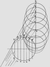
The False Perspective
Given the special constraints on introducing the false vault, Pozzo set out from the axiom that the circles ringing the vault up to the lantern must be seen in perspective as circles [19]. He applied this axiom equally in both cases shown in Figure 49 of his treatise, “quando il punto dell’occhio è fuori del mezzo… per aver l‘occhio in mezzo,” from which we may conclude that an upward observation (di sotto in sù) is effected both when the observer’s view coincides with the vault’s axis of symmetry (linea del mezzo) and when it does not. We may infer from the vault drawings in the treatise [20] that the system of visuals referenced to the eye (punto dell‘occhio) resulted in an oblique position relative the base of the finta copola, that is, the Pozzo defined a the linea del taglio. The result is that the observer’s symmetrical sight line for Saint Ignatius is not projected orthogonally to the perspective plane, because, strictly speaking, that would place it perpendicular to the nave ceiling and not to the vault.
This peculiarity in the construction brought us to pose the methodological question of why Pozzo did not execute the perspective outline on the perpendicular plane to the observer’s symmetrical sight line, as can be clearly deduced from Figures 50, 51, and 52 of the secondo tomo? We believe that that premise would have led to the conclusion that series of circles ringing the vault necessarily appear to the observer as discrete ellipses —even though on the pictoric surface the circles are sempre perfetti, e fatti col compasso. This is the paradox of the Sant’Ignazio finta cupola: circles are drawn but they should be perceived as ellipses.
In the frescoes of the corridio della Casa profesa del Gesù “Qui, per la prima volta, Pozzo aveva messo in opera un sistema di deformazioni ottiche pittori.” [21] This system allowed for creation of Saint Igantius’s earthly existence and celestial glory in anamorphic perspective on the walls and ceiling. Pozzo chose the center of the hallway to be the stable observation point, (Figure 101, secondo tomo), contrary to the precepts of Egnazio Danti and Abraham Bosse who recommended in these circumstances dividing the length of the underside into panels, each with its own viewpoint. One cannot help but notice that Pozzo did not dedicate a single one of the samples of anamorphic perspective in an environment characterized by experimentation and play with this new perspective. Even Pozzo himself had been in contact with Rome’s minimalist friars of Santa Trinità dei Monti, and Athanasius Kircher’s 1671 publication Ars Magna lucis et umbrae was still quite recent and had included some catottriche machines with his system of mirrors to multiply space.
On two occasions the author has unsuccessfully attempted to grasp the illusory effect in situ, (1992 and 2001). Positioning oneself at the precise observation point, something appears to be missing to adjust the eye to the pictorial plane. One deficiency in Pozzo’s treatise is a lack of indications for the observer’s location and the direction of sight to appreciate the vault’s illusory effect. Theoretically, the effect should be perceived by gazing at the center of the pictoric plane, serving as the point of reference from which to examine it in greater detail. Looking di sotto in sù, it is reasonable to place oneself before the pictoric plane and raise one’s eyes, or —although it may seem less logical— to turn backward and stretch to rotate one’s head to the visual center. The difference is that effect is much more powerful when one is backward, looking at the painting upside down.
Anamorphic perspective, just as linear perspective, should be perceived by directing one’s line of sight to the center of the pictoric surface, with the result of it coinciding with the center of the visual field. Even in François Nicéron’s extremely distorted scenes S. Francesco di Paola in preghiera, the line of sight is directed toward the center of the pictoric surface that does not coincide with the mural’s physical center.
Figure 10
Geometrical Outline of the False
Vault
Figure 10 |
For several reasons we decided to analyze the geometric construction of the vault in the Roman Collegium rather than the Saint Igantius, even though both were illustrated in Perspectiva, Pictorum…. One consideration was that the geometrical information on the Roman Collegium is sufficient to our purposes, notwithstanding Pozzo’s warning of its lacking the corbels. Another is that the one at Saint Igantius is incomplete; the architectural section (Figure 94, primo tomo) does not indicate the observer’s station, nor does the architectural section correspond in each and every one of its parts to that represented in the painting. For example, the perimetral cornice’s modillions are missing [22]. Also, a faithful, large-format photographic reproduction would be indispensable to determining the original strokes in the painting, which is not only difficult but hazardous because it has been restored twice [23] and we cannot know whether the original has been compromised. Finally, the vault of the Roman Collegium is more famous for popularizing the excellent figure in the treatise. Despite these considerations, our geometric analysis is valid not only for one but for both works, because both were outlined under the same perspective procedure.
We shall pursue our step-by-step analysis in accordance with the author’s Modular Perspective [24], combining its two methods of application under the geometric and numeric procedures, so that the reader may easily visualize the vault’s perspective construction. We shall begin with Figure 10.
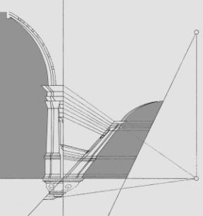
1. To trace the vault section according to Figure 51 of Volume II (secondo tomo), the proportions are restored to the true shape and dimensions of the points registered on line A-B. These are taken to the PPL, as shown in Figure 10. Since the original figure does not have corbels or the cornice, we calculated them directly from Pozzo’s perspective.
2. Once the vault section has been defined, and basing ourselves on the observation point (O), the observer’s visual field (VF) is traced in symmetrical plane Y (SPLY), bounded by the visuals grazing the pictorial plane (pPl), as shown in Figure 11a.
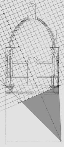
3. Angle VF is
bisected to obtain the observer visual of symmetry (VS). By definition, VS
guarantees that the observer’s line of sight passes through the center of
the perspective plane (PPL), which in this case will not correspond to the
dimensional center of pPl.
Figure 11a
4. The PPL is drawn perpendicular to VS, using for reference the right grazing visual of VF, exactly at the vault’s degree of slant.
5. SPLY is modulated from PPL. This modulation, due to its true shape and size, will allow reading of coordinates (Y, P).
6. Because the perspective of the vault must be necessarily be executed on pPl (the material plane), we shall say that pPl also represents the image’s anamorphic plane (AnPl) because VS intersects it at an oblique projection. Strictly speaking, the perspective of the false vault must be executed in anamorphic projection.
7. To aid in the procedure, the architectural plan of the vault in symmetrical plane X (SPLX) is included (see Figure 11b). Only the X coordinates will be read in this plane, because the P coordinates (depth) are not at their true shape and dimensions.
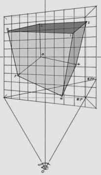
8. The construction of the AnPl is calculated from the PPL. Note that AnPl corresponds to the PPL’s projection, as shown in Figure 12.
9. The Modular Perspective method uses the following two equations to calculate the image in AnPl.
Xo = X.d/P+d (1)
Yo = Y.d/P+d (2)
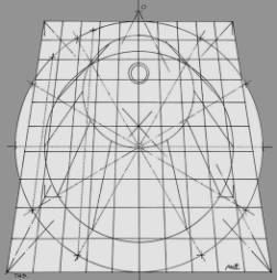
10. The paradox of the false vault is that the perspective of the circles in AnPl is constant, that is, circles are drawn. Yet when the observer takes the proper station before either the drawing or the painting, these circles become discreet ellipses. In a word, circles are drawn but ovals are seen. How can this paradox be demonstrated?
The reasoning is straightforward. While AnPl contains the drawing of the image, PPL represents the image to be perceived. Keep in mind that pPl may or may not coincide with PPL. The result is a virtual image not contained in PPL but projected from it. To calculate the image in this plane we follow the procedure described previously for AnPl up through step 5, skipping steps 6 and 8, applying equations 1 and 2 in step 9, as shown in Figure 13.
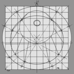
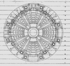
The perspective values (Xo, Yo) obtained from these equations are valid for both AnPl and PPL because they are projectually analogous. The reader may graphically prove how the (Xo, Yo) values for every point in Figure 12 correspond with Figure 13. Note in both Drawings how the PPL lattice describes perfect squares for discrete ellipses and AnPl describes trapezoids for perfect circles. It is not for nothing perspective remains l’enganno dell’occhio, but now we would more likely say, l’enganno della forma. Finally we offer in Figure 14 the perspective of the Roman Collegium vault according to the Modular Perspective method. We have turned upside down its position for the reader may perceive this way the architectural illusory full effect.
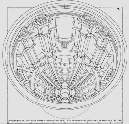
Please, look at the ‘eye’ of the drawing meanwhile the distance is adjusted properly. Hold in this position and moves your sight upside down over the drawing until the ellipses change into a perfect tridimensional circles, amazing isn’t! My assistant, Jesús Manzanares, and I had enjoy very much the outlining of this challenging perspective.
References
[1] The source consulted for this brief review was: Kim H. Veltman, “Perspective, Anamorphosis and Vision” (Marburger Jahrbuch, Vol. 21, 1986, pp. 93-117). Pierre Descargues, Perspective (New York: Harry N. Abrams, 1977).
[2] Roy R. Behrens, “The Artistic and Scientific Collaboration of Blanche Ames Ames and Adelbert Ames II,” Leonardo, Vol. 31, No. 1, pp. 47-54, 1998.
[3] Daniel L. Collins, “Anamorphosis and the Eccentric Observer: Inverted Perspective and Construction of the Gaze,” Leonardo, Vol. 25, No. 1, pp. 73-82, 1992.
[4] Tomás García-Salgado, “La Perspectiva de la Ultima Cena de Leonardo da Vinci,” Ciencia y Desarrollo, Vol. XXIV, No. 143, 1998, pp. 34-47.
[5] Veltman addresses this question directly in his essay [1] p. 98. “What then is the difference between a regular perspectival painting and anamorphic one if both contain distortions and both are profitably viewed from the side?” Veltman’s argument is based on analysis of the distortions in the linear perspective when the observer is not at the vantagepoint. For example, analyze the lateral view (or foreshortened anamorphically) of the famous de Berlin, Baltimore, and Urbino Panels that among other things demonstrate that the depth effect is considerably augmented rather than diminished.
[6] Andrea Pozzo, Perspectiva, Pictorum et Architectorum (Roma: Primo Tomo, 1693; Secondo Tomo, 1700). Figure 71 (P.T.), Teatro delle Nozze di Cana Galilea fatto nella Chiesa del Gesù di Roma l’anno1685 per le 40 ore.
[7] Marina Carta, Andrea Pozzo (Milano: Electa, 1996, edizione a cura di Vittorio De Feo e Vittorio Martinelli), p. 63: “La chiesa di Sant’Ignazio, dedicata al fondatore della compagnia, doveva testimoniare la continuità della missione di divulgazione della fede e la forza dell’organizzazione dell’ordine. L’impegno artistico di Pozzo era finalizzato a questa tensione ideologica ed era ispirato da regole, che erroneamente la storia dell’arte ancora considera effimere, derivate da rigorosi studi geometrici e prospettici.”
[8] The NIV Bible, John 2: 1-9.
[9] Pozzo [6], Secondo Tomo, p. 66.
[10] Tomás García-Salgado, “Ghirlandaio,” Ciencia y Desarrollo No. 157, Vol. XXVII, pp. 40-53, 2001.
[11] Zaccaria Carlucci S. J., La Chiesa di S. Ignazio di Loyola (Proprietà riservata della Chiesa di S. Ignazio, 1995), p. 16: “La chiesa di S. Ignazio di Loyola in Roma è nata come chiesa del Collegio Romano, prestigioso istituto didattico-culturale, modello di tutti i collegi della Compagni di Gesù nel mondo, per gesuiti ed esterni.”
[12] Carlucci [11], p. 39.
[13] Carlucci [11], p. 42.
[14] Carlucci [11], p. 45.
[15] Carlucci [11], Note 40, p. 46.
[16] Carlucci [11]: Note 42, p. 47: “È stato scritto che la finta cupola fu dipinta nel salone del Collegio; ma ciò era possibile solo per i preparativi: il salone e largo circa 12 metri e no ci si poteva stendere una tela di m. 17 di diametro; l’unico punto possibile era al centro della crociera.”
[17] El graticolato (the network tracing on the canvas) may be appreciated by the naked eye with well-lit photographs.
[18] The architectural outline of the Collegio Romano Vault, which Pozzo repeats in both volumes of his work, is based on the vanishing (or foreshortened) profile of the vault to determine the position and depth degradation of the circles, using the vanishing point to control the rest of the lines.
[19] Pozzo [6], Secondo Tomo, Figure 49: Istruzione, per fare le Cupole di sotto in sù. “Se le Architetture rotonde, messe in prospettiva, e vedute in faccia, sono sì difficili a ben farsi, per aver a condut la mano da punto a punto per tirar le linee curve, non possibili a descriversi col compasso, altretanto sono facili le Architetture rotonde di sotto in sù: perchè i circoli, ancorchè digradati, son sempre perfetti, e fatti col compasso.”
[20] Pozzo [6], Secondo Tomo, Figures: 90 (Cupola in Prospettiva di sotto in sù), 91 (Cupola de la figura 90. co’suoi chiari, e scuri), and 92 (Cupola ottangolare) from the Primo Tomo. Figures 49 (Istruzione, per fare le Cupole di sotto in sù), 50 (Cupola in piccolo di sotto in sù), 51 (Cupola del Collegio Romano, con la regola del primo Tomo), 52 (Cupola del Collegio Romano con la presente regola), 53 (Cupola del Collegio Romano ombreggiata), and 54 (Cupola di diversa figura) from the Secondo Tomo.
[21] Daniela Gallavotti Cavallero, Andrea Pozzo (Milano: Electa, 1996, edizione a cura di Vittorio De Feo e Vittorio Martinelli), pp. 42-49.
[22] The intelaiautra deals precisely with projecting the vault from the corbels that bear the column pedestals, such that the perimetral cornice is the pictoral element that resolves its mounting. Nonetheless, the cornice visibly presents line complication caused by the stairstepped moldings: the perimetral perspective of the moldings does not appear to correspond to their section. We plan to analyze this line complication in detail in another study. In fact, the elaborate design of the perspective on the perimetral cornice is quite complicated, even when referenced from the circles.
[23] Carlucci [11], p. 53: “In un funerale per un membro della famiglia reale spagnola un colossale catafalco prese fuoco e danneggiò irrimediabilmente la finta cupola, che dovette essere riffata nel 1823. Questa copia fu squarciata dall’esplosione di una polveriera militare del 1891 e nascosta poi con un telone scuro sottostante. Finalmente tra il 1962 e il 1963, per iniziativa del Soprintendente Prof. Emilio Lavagnino, fu restaurata dal Prof. Giuseppe Cellini.”
[24] For further elucidation on the Modular Perspective method, reference these works by the author: (1) Perspectiva Modular: Aplicación al Diseño Arquitectónico (México: Trillas, 1992), and (2) “A Modular Network Perspective vs. Vectorial Models,” Leonardo (UK: Pergamon Press, 1988), Vol. 21, No. 3, pp. 277-284.
Credits
Spanish-English translation by Nevin Siders (CELE, UNAM).
Drawings: 1, 2,… 8b, 12 and 13 by the author; 9 by Andrea Pozzo’s book; 10, 11 and 14 by the author and Jesús Manzanares.