THE GEOMETRY OF THE
PANTHEON’S VAULT
Dr. Tomás García Salgado
BSArch, MSArch, PhD, UNAMprize, SNI nIII.
Faculty of Architecture, National Autonomus University
of México.
1 Geometry of the Vault, 2 Perspective of
the Vault, 3 Perspective Outline.
1 Geometry of the Vault
From the point of view of perspective,
the only noteworthy item of the interior of the vault of the Pantheon is the
visual effect produced by the geometric composition of the coffers. In order to
draw the perspective outline of the interior of the Pantheon, it was essential
to first understand how the vault was built, since the presence of the coffers
did not arise from a decorative idea but rather from the need to reduce the
weight of the vault, while maintaining a cross-section that was sufficiently
robust to support its own weight. If we assume the hypothesis that the vault
was built using an arched framework supported by the great cornice and set out
radially, then the constructive outline of the coffers must have been
controlled by means of molds built on the framework itself. In addition, it is
possible that such construction was carried out at the floor level using a
template that describes at least half of the hemisphere.
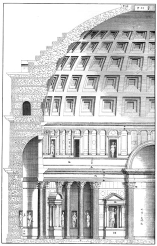
Palladio interpreted the inside slopes of the
coffered ceiling of the vault cross-section as a radial outline at the level of
the great cornice (see Fig. 1). In surveys subsequent to those of Palladio, as well as in recent
photographic studies, it can be seen that the inferior soffit slopes of the
mitered joints that form the coffered ceiling seem to be directed towards the
floor, that is, the view is flush with respect to the inferior soffit planes,
while the superior soffit slopes seem to follow the radial outline at the level
of the cornice. In order to determine the geometric outline of the coffers, it
is essential to obtain the exact measurement in-situ. Such geometric evidence
was not available for this study. However, our objective was not to obtain a
perspective that faithfully represented the real construction, but rather to
demonstrate how to approach a complex problem of perspective outline using the
generative methods of distance vanishing point and diagonal vanishing point. In
view of this, we considered it was sufficient to base our study on the
information obtained from the drawing of W. L. MacDonald [1], as well as on
photographs taken and observations made in-situ by the author (02.1994).
There are two explanations for the emphasized
construction of the inferior soffit slopes of the coffered ceiling of the
vault. The first explanation suggests that this particularity might be due to
the constructive procedure itself, while the second explanation suggests that
there may have been a deliberate intention of formal appearance. In the first
case, it is possible that Agippa emphasized the inferior soffit slope
vertically, to ensure the stability of the casting of the concrete, assuming
that the vault was structured and poured from the base up until it was closed
at the oculus. In the second case, if the form that was adopted did not follow
from a constructive consideration, it is possible that the intention of the
aspect of the coffered ceiling was to avoid that the soffits remain hidden from
the observer, thus avoiding an unaesthetic appearance and the accumulation of
dust. In this respect, and based
on a detailed photograph of the coffered ceiling (see Photograph 1), Henri Stierlin [2] commented:
“Note the subtlety of the displacement toward the top of the
strengthening elements in order to correct the optical distortion due to the
observer’s position on the ground and not at the level of the
hemisphere”.
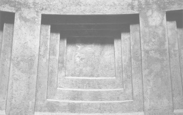
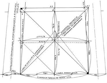
An analysis of Stierlin’s photograph (see
photo 1), by means of Fig. 2,
leads to infer that all the coffered ceilings have a trapezoidal outline that
can be made to fit in a square if the length of the longer base is averaged
with the length of the shorter base. Since we do not know if the photograph was
taken from a position perpendicular to the plane of the coffered ceiling, it is
impossible to be certain that the analytic outline is correct. However, the
photograph is demonstrative with respect to the top shift of the center of the
outline from (c) to (c’) for the inferior soffit slopes. In the same
figure, it can be observed that the outline of the superior soffit slopes of
the coffered ceiling tends to follow the reference of the upper diagonals of
the trapezium.
The reason for assuming that the coffered
ceilings arise from a square whose base is governed by the diminishing outline
of the 28 meridians, is that the coffered ceilings do not correspond to a
readily identifiable constant or progressive radial outline, whether referred
to the center of the sphere or to its projection on the floor. Therefore, our
hypothesis for the outline of five courses of the coffered ceilings assumes
that their construction followed a physical deduction on the meridian lines,
based on some simple geometric rule for the outline of the framework of the
coffered ceilings. In Fig. 6,
if the profile of the coffer of the first course is taken as a reference and
then shifted successively to the others, it can be observed that the inferior
and superior soffit slopes tend to be the same. This suggests that some type of
master mold was used to build the framework and that it was simply adjusted to
the dimensions of each meridian course. Assuming that a measurement in-situ
were to show that the slopes are the same, the reason for emphasizing the
inferior soffit slopes would still remain unexplained. Although we have
suggested two possible explanations from the constructive and formal points of
view, neither is sufficiently demonstrative. So, for the time being, we will
let the Pantheon keep some of the secrets of its construction.
2 Perspective of the Vault
Several treatise writers, painters and
geometrists have attempted the outline of the interior views of the Pantheon.
Giovanni Paolo (c. 1750), Pannini, Gian and Francesco Piranesi (XVIII century)
made drawings and engravings of such a high quality that they are considered to
be historical documents. Among the writers, Piero della Francesca studied a
problem similar to that of the construction of the perspective of the Pantheon
[3]. Although the dimensions of his problem were smaller, it is interesting to
analyse his method of outline. However, after studying the outlines of these
works, we concluded that none of them offer an exact geometric description.
This may be because their designers did not follow a method that would allow
them to directly control the perspective outline. The traditional methods of
perspective become very intricate and inexact when applied to deducing
subtleties such as the sweep of the vault soffits, in other words, when
generating the perspective geometry.
In view of the above, we became
interested in the perspective outline of the vault, with the purpose of testing
a method that would simplify its execution. However, before attempting any
outline based on the hypothesis of formal appearance or constructive procedure,
we needed to establish the geometric construction of the coffered ceiling in a
consistent manner. To this end, we found it very useful to study not only the
historical background of the Pantheon but also the Roman architecture of the
time, when vault-building technology reached its climax.
Agrippa or Hadrian solved by some means
the problem for the construction of the framework of the coffered ceiling, to
achieve their uniformity, which, as mentioned above, suggests the use of molds.
However, such molds must have been based on an established outline or pattern.
When faced with a similar problem in my practice as an architect, I have always
sought that the outline of something that is to be built repeatedly be simple
to execute. For example, if we had to determine the outline of the five master
frameworks that form a meridian course, the first thought would be to use a
sole principle to generate the entire woodwork. The principle would be simple,
easy to apply in situ,
and deduced as a function of the decreasing value of the meridian course. This reasoning can be explained in the
following manner by means of Fig. 3.
2.1
Assuming that the intention of the outline [4] is to design the coffered
ceiling with a proportional appearance close to that of a square, whether
slightly larger or smaller than the trapezium to be contained, the first step
would be to construct the reference square as a function of the proportional
modulation of the parallel line where its base rests, such that the height of
the trapezium does not surpass the width of the base of the coffer.
2.2
If the first parallel line is taken as the base level of any of the 28 meridian
courses, as shown in Fig. 3,
it can be observed that the outline of the coffer forms a trapezium that can be
inscribed in a square whose diagonals coincide, at least in the figure, with
those of the inscribed trapezium. It can be shown that the horizontal line that
runs through the intersection of the diagonals of the trapezium is equal to the
average of the bases of the trapezium. Given that, strictly speaking, the
trapezium of the coffer is slightly smaller than the inscribed trapezium, its
horizontal line, which is the average of its bases, will be slightly greater
than the inscribed trapezium.
2.3
One way of avoiding this small difference would be to use a second square whose
outline, according to Fig. 2,
would be deduced by drawing the first square with its diagonals, as described
in item two above, defining the height of the trapezium of the coffer and
transporting it horizontally to the height of the intersection of the
diagonals, such that the intersection of this horizontal line and the meridian
lines defines the construction of the second square.
2.4
Both procedures are very similar. In fact, a third procedure could be proposed
if the exact measurement of a meridian course were available. However, our
numerical calculation for a meridian course representing the values obtained
from an orthographic projection [5], revealed a trend of proportionality in the
five levels that correspond to the coffered ceiling. Thus, Figs. 2 and 3 can be considered to be an acceptable hypothesis of
approximation.
3 Perspective Outline
Since our objective is to find a method
for simplifying the perspective outline, we apply the method of the diagonal
vanishing point, which, given that the geometric figure in question is a square
into which the circles of the parallel courses can be successively inscribed,
is also compatible with the method of the distance vanishing point, because
both vanishing points, meet at the same point on the visual horizon. These two
Renaissance methods of the diagonal vanishing point and the distance vanishing
point are applied here under the author’s Modular Method. As shown below,
the exact outline of the coffers is generated by iterating the same procedure,
regardless of their position in the vault.
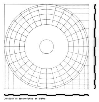
3.1
The five intervals of the parallel
circles are drawn in a horizontal projection, and these in turn are divided
into 28 meridian intervals, as shown in Fig. 4. Since the outline procedure consists in the
successive construction of each parallel circle, it is suitable to deduce for
each one the stencils that determine the position of the meridian lines, so
that, in order to execute the outline of all the parallel circles, this step of
the procedure must be repeated six times.
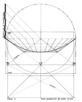
3.2
The section of the building is
drawn with the observer located at a distance that is slightly shorter than the
radius of the vault, that is, with an angle of observation that is a little
over 90°, as shown in Fig. 5. Subsequently, the height of the observer on which
the visual horizon will run is determined. The visual horizon contains the
vanishing point and the position of the symmetry visual is fixed at the center
of the scene.
3.3
The distance vanishing point is determined on the visual horizon precisely
above the limit of the perspective plane and, by symmetry, this vanishing point
can also be represented on the left-hand side of the visual horizon. Since, as
mentioned above, in this case the distance vanishing point coincides with the
diagonal vanishing point, this vanishing point is used to deduce the depths of
the meridian circles to be obtained on each of the parallel circles.
3.4
The height of each parallel circle is marked in the schematic section of Fig. 5. The first of these marks coincides with
the height of the great cornice which, in turn, defines the base of the vault.
As can be observed in this figure, only half of the first parallel circle is
shown, since the intention is to construct the perspective of half of the
vault, as if the Pantheon were cut in half.
3.5
In Fig. 4, in the
margins of the plan, are marked some stencils which represent the modular
divisions of the meridian circles. The outline of these stencils is repeated
for each parallel circle, since, by being concentric, the modulation of the
meridian circles is variable. The figure only illustrates the first circle,
with the understanding that the outline of the other five circles is generated
identically.
3.6
The modulation of the meridian circles in the perspective plane is obtained by
transporting the stencil of Fig. 4 to Fig. 5. For clarity, the stencil is positioned vertically at
the level of the first parallel circle. In practice, this procedure is
simplified by marking the modulations directly on the horizontal line of the
plane that contains the parallel semicircle. This horizontal plane represents
half of the square that contains the semicircle whose perspective is to be represented,
thus, the perspective is obtained exactly by means of the orthogonal
conjugation of the stencils, as shown in Fig. 5. In this figure, it is important to note
that the deduction of the modular depths of the stencil is obtained be means of
the diagonal vanishing point, whose principle guarantees the correct generation
in depth of the modular values given in the perspective plane.
3.7
This procedure is repeated until the outline of the parallel semicircles is
complete. Subsequently, the entire outline of the modulation of the vault,
forming the hemispherical reticle of all the coffers, is made.
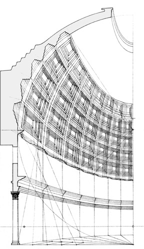
3.8
The detailed perspective of the coffered ceiling is obtained from the left half
of the perspective plane, given that, by symmetry, the lowering of this
projection produces the entire outline. Fig. 6
provides details of the constructive section of the coffered ceilings; the outline of the superior and
inferior soffit slopes is marked on the profile, while the vertical soffits of
all the meridian intervals are marked on the outline of the first parallel
semicircle. With these two simple references, that is, by intersecting in
perspective the parallel outlines with the meridian outlines, it is possible to
generate the perspective deduction of the coffered ceiling. Since this
procedure is carried out by means of perspective outlines, it is referred to as
a direct deduction procedure. If the deduction were made by relating plan and
elevation, it would be necessary to carry out at least six horizontal cross-sections,
with the disadvantage that the dimensions of the cross-sections of the coffered
ceiling would be incorrect due to their angular variation with respect to the
vault profile.
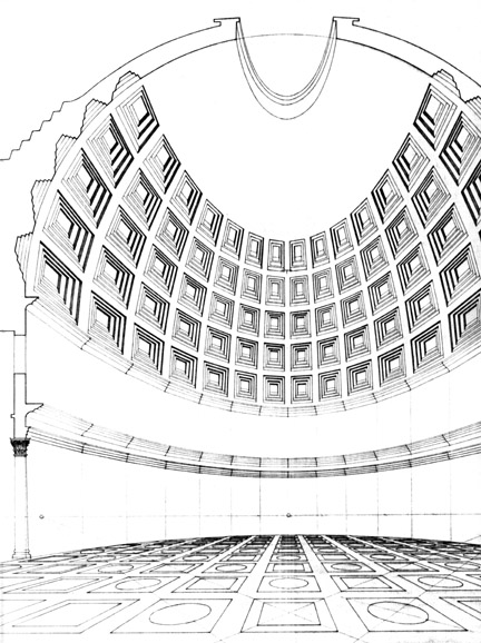
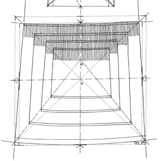
3.9
Finally, Fig. 7 shows the perspective of the vault as a
geometric discourse whose central theme, the coffer, moves only in two
directions on its hemispherical surface, to give formal expression to its sense
of composition. Such formal
expression is supported by the pre-Vitruvian principle of the unity of the
parts of a whole and the constructive truth of the form. Just as the orifices
(or windows) of the skull of the allosaurus lessened the weight of that
dinosaur’s head, thus avoiding an imbalance in the animal’s weight,
while allowing for large jaws for the purpose of devouring, the coffers of the
vault bear witness to the constructive truth of its great mass, which exists
more for the sake of appearance than out of a need to “survive”.
Our essay emphasized the form and construction of the vault over its perspective
representation, since, ultimately, solving its outline merely requires applying
the principles of perspective with a certain degree of mastery. However, in
architecture, a study of the origin of form, such as that presented here, leads
to a better understanding of the generation of the geometry of the form in
space.
Notes and References
[1] W. L. MacDonald, The Pantheon (USA: Harvard Univ. Press, 1976), pp.
30-31.
[2] Henri Stierlin, The Roman Empire
(Italy: Taschen Verlag GmBH, 1996), pp. 158-159 (photo 1).
[3] Piero della Francesca, De
prospetiva Pingendi,
Edizione critica a cura di G. Nicco-Fasola (Firenze: Casa Editrice Le Lettere,
1984).
[4] Even if there had been alternate
approaches for envelopment, other than the use of a square, some rule of
proportionality must have been defined. Even before Vitruvius, the principle of
proportions governed architectural composition, elements and decoration (sense
of unity).
[5] Based on the fact that the width of
the vault is 43.28 m, the meridian lines would measure 33.99 m from the cornice
to the center of the oculus.
From the cornice to the horizontal axes of the coffered ceilings the distances
would be 5.67 m, 4.53 m, 3.97 m, 3.59 m, and 3.21 m for the five rows, 8.50 m
for the smooth surface, and 4.53 m for the oculus. An estimate of the distances
between coffers is, in the same order, 0.91 m, 4.38 m, 0.76 m, 3.82 m, 0.66 m,
3.35 m, 0.57 m, 3.07 m, 0.47 m, 2.88 m, 0.19 m, for the five rows. The widths
of the lines parallel to the axes are 4.85 m, 4.69 m, 4.33 m, 3.85 m, 3.31 m,
2.73 m, and the widths of the coffers are 3.88 - 3.77 m, 3.74 - 3.49 m, 3.43 -
3.11 m, 3.05 - 2.68 m, 2.62 - 2.22 m. The orthographic interpretation of these
values is consistent, since the lines of the outline tend to be continuous. The
values will be reviewed at a later date, since an exact measurement or, at
least, a photometric substitution study, is essential to minimize the margin of
error.
Credits
Photograph
1, Henri Stierlin, see reference [2].
Fig.
1 Andrea Palladio,
Pantheon’s Section from I Quattro Libri dell’Architettura, LVII.
Fig.
2 Geometrical
analisys of the coffered ceilings by TGS.
Fig.
3 The outline
principle to generate the woodwork, hypothesis by TGS.
Fig.
4 Plan of the
parallel circles and the 28 meridian intervals by TGS.
Fig.
5 The deduction of
the modular depths is obtained be means of the diagonal vanishing point. This
application is a variant of the author’s method: Perspectiva Modular.
Fig.
6 Perspective of the
left half of the perspective plane the author and
Jesús M.
Fig. 7 Perspective of the vault by the author and Jesús M.