GA 2002
Modular Perspective as a Method for
Generative Design
Dr. Tomás García-Salgado
BArch, MSArch, PhD, UNAM prize, SNI nIII
Faculty of Architecture- National
Autonomous University of México
E-mail tgsalgado@perspectivegeometry.com
Abstract
Apparently there are many methods for perspective but if we categorize them there are just a few. Some criterions of classification relate perspective to the so-called 1-point, 2-point and 3-point methods, others —more formally— to projective geometry, descriptive geometry or vectorial algebra. Of course we cannot forget to mention the early treatises on perspective such as Alberti’s Della Pittura or Piero’s De Prospectiva Pingendi, which escapes any classification. Our aim on this article is not precisely to solve the classification problem rather we propose a new comprehensive method for perspective, capable of 3D representation without using vanishing points.
The modular perspective method allows us to work in true three-dimensionality on the perspective plane (PPl). We will explain how to measure directly on the PPl the triad coordinates (x, y, p) of a given point into the visual space, and how to play with the symmetrical planes X and Y (SPl X/Y) in order to generate or recover data. Finally we will explain how to employ modular perspective in generative design formal-process through an example of application.
1. Spatial
Perspective Versus Object’s Perspective
Our first analysis is focused on the difference between the perspective of the observer’s visual space and the perspective of the objects. Alberti’s method for instance, describes the observer’s visual space by means of a reticulated grid —as a measuring system; opposed to traditional methods that pursuit solving the perspective of the objects alone. These methods lead us to understand perspective through two different models: The Albertian, as a geometrical system of human vision and the traditional as a repertory of geometric recipes to solve figures in perspective.
But what does spatial perspective versus object’s perspective mean? A scientific explanation can be given through the human vision itself, but our purpose here is not to study the neuropsychological processes of vision —a very complex process indeed—, rather we pursue to interpret human vision throughout geometrical concepts.
From Renaissance perspective we inherited the visual pyramid model —with its cutting plane or window. But this model has an important feature not very well understood even nowadays, and that is that only one vanishing point can be located in it. In other words we can ask: How many vanishing points does the visual pyramid has? A question that challenges us to explain how perspective can be conceptualized through the so-called vanishing points methods. As we know these methods are based in the cube’s geometric properties instead of a model of the human vision [1].
The modular perspective model represents the observer’s visual space in the same manner the Albertian visual pyramid does, in such a way that our sight line runs from the pyramid’s vertex toward infinity. The symmetrical plane X (SPl X), the symmetrical plane Y (SPl Y) and the PPl are the basic components of the modular perspective model, as it is show in Figure 1.
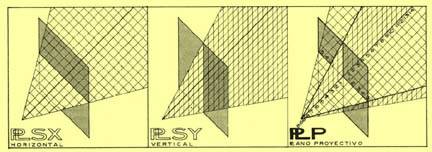
What the observer perceives through the PPl is the object’s apparent size because its length, width and height dimensions change as we move forwards or backwards. In any case the apparent size of what we perceive is ruled by visual triangles. This geometrical feature means that all visual triangles are proportional and thereby the PPl can be placed it at any depth in the model.
Notice that the observer (o) and the SPl X/Y vertex share the same origin —contrary to those vectorial models in which two origins are required—, so we can easily measure the width, height and depth (x, y, p) of any given point into the visual space. As the three planes of our model correlate to each other, the coordinates (x, y, p) can be read directly on the PPl. The remaining question here is: where the vanishing point (pf) should be placed? As the reader might suppose, the intersection of the SPl X/Y determines the symmetrical sight line (vs), where (o) and (pf) are located at its ending points. In other words, the point at the center of PPl represents the (pf). This geometrical feature allows sketching in perspective in a true three-dimensional plane, that is, on the PPl.
2. Measuring
Points on the PPl
Our method consists on determine the (x, y, p) coordinates of a point (Pn) in the space under the modular perspective geometric procedure —since the numeric one is more suitable for computer applications. There are five cases of punctual perspective projection into the PPl. We will present here in full description the first case, since the other four cases will be posted on the Internet soon [2]. Our description, rather practical than theoretical, starts with the problem statement and then after with its solution.
Case 1. Problem
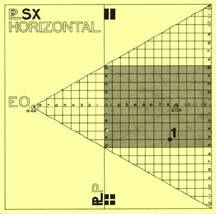
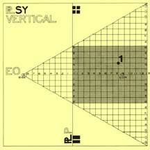
This case occurs when the values of (x) as well as those of (y) are not greater than ±5 m, and when (p) has a positive value. As can be seen through the SPl X/Y, in Figures 2 and 3, the coordinates of point P1 are plotted within the shaded area of both planes.
Case 1. Solution
This case is the easiest of all to solve. When (x) and (y) are less than or equal to ±5 m, they are drawn directly using the Salgado Modular Scale (RMS). We can see in Figure 4 how to draw P1 in perspective:
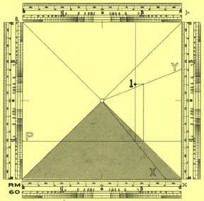
- x = 4.00 m, measure on lower border and take to (pf).
- p = 8.00 m, measure on the left border and draw it the width of the visual field, where it intersects (x) draw as ^ to (p). The problem now consists on finding (y) on this ^.
- y = 2.00 m, measure in right border and take to (pf). At the intersection of (p) with the diagonal raise another ^ to (p) until it meets (y), from there draw a horizontal line to the ^ (x, p), and this intersection determines P1 in perspective.
I am aware that this could sounds very much mechanical because we are not using simple words to tell what is going on the PPl, but this is the only way to avoid mistakes. Nevertheless, lets try another manner of understanding what we did to obtain P1:
- Imagining the PPl, as a sheet of glass in front of you and a point behind it, then try to follow by sight its three spatial coordinates into the real space while observing the PPl, and you will realize exactly what we did above to obtain P1 in perspective. Repeating this procedure for other points will confirm you that (x) and (y) always vanish to (pf) while (p) relates to them transversally in depth.
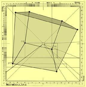
Lets see now the classical example of a cube in perspective this time without using any vanishing points aid but the (pf) alone, that is, taking the cube as a referred object into the visual field. Figures 5 and 6 show us the cube’s projection on the SPl X/Y, so the (x, y, p) coordinates of each of its point can be read onto them.
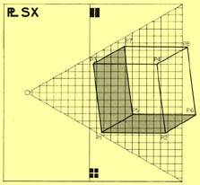
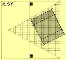
Do not worry about the geometrical accuracy in reading coordinates on these planes since our visual-measuring approximation is reliable enough to accomplish this task. For instance, when reading P3 coordinates we can have:
x ≈ – 4.05 or – 4.10
y ≈ 4.40 or 4.50
p ≈ 0.50 or 0.60
When the SPl X/Y are larger than the illustrations posted here the coordinates read would perform the same way as if using the customary scale-meter, which in our case would be done through the RMS complementary scales.
Remember that we are employing modular-scale values all the time, which means that the cube can take any size depending on its pre-establish dimensional equivalence, so our example can either be as short as a cube-toy or as large as La Grand Arche building (Paris). You can image these two extreme examples on the cube’s Figure 7.
The three scales on the RMS can be enlarged or shortened as we choose beforehand. If you want to render a perspective on a mural surface you can outline it right there on the wall, avoiding the inaccurate quadratura procedure or wondering where to pass through on the contiguous walls to locate the vanishing points you might need. The RMS more noticeable advantage is the freedom we get in controlling the drawing’s size, as big or small we wanted to.
It is easy to render a perspective by using the SPl X/Y data. This technique is part of the students training in modular perspective in order to enhance their spatial abilities. They have to read the SPl X/Y data in order to interpret it on the PPl, that is, to learn how the 2D-3D transformation works. In the outmost level of training, students learn how to visualize objects in 3D only, by attempting to design architectural forms directly on the PPl, the same way they use to do in planar projections. Thinking in two-dimensions can be complicated some times but thinking in three-dimensions is a real challenge, due to the fact that our brain’s right side must operate highly complex spatial relations.
3. Modular Perspective and Generative Design
I do not know what could it be for other schools of architecture, but at mine —and for many years until nowadays— the perspective outlining of a project is the last thing to do. In other words, the customary design process is born in 2D sketches, matures either way, and gets old in 3D. So, our perspective’s vangelio suggests for it to be born in 3D at once.
Celestino Soddu quotes in From Forming to Transforming: “In every project there is a first step. The designer knows that his first act has a precise purpose: he has to trace a system of relationships that must be adaptable to each possible development.” [3] Certainly the idea must be grasped as the first act of design, but what matters more is the way we choose to approach it. As we know creativity involves the utmost complex brain operations not susceptible for translation into a method of any sort, so there can be many ways to approach the idea. The more we can say about it are generalities such as choosing between sketching in 2D or in 3D, a choice that depends upon our spatial abilities to perform the one or the other.
For sketching an idea, either in 2D or in 3D, computers are not yet suitable for problems solving into the vast field of creativity, that is to say, they seem not to enhance human creativity, and even more, as Van Doren says about companion computers: “They will make life very pleasant, but they will no much change, and certainly not improve, human nature.” [4] They are just tremendous processing tools but incapable of really helping the act of creativity that involves personal perceptions and emotions. Artificial intelligence (AI) plays an important roll in computer systems, pursuing the way to emulate human behavior. Burton points out that: “Both AI (particularly symbolic AI) and drawing theory came to model human behavior as information processing.” [5] Cleary the new lead to follow seems to be the so-called drawing theory that becomes a seriously research topic for neuropsychologists, meanwhile designers starts to be interested on the subject too.
When a children is asked to draw that what he is looking at, he draws what he knows about that thing instead of what he actually is seeing, because he has not been training to interpret and play with spatial relations. But when an architect is asked to draw that which does not even exist is a big challenge, because he does not know from where to grasp an image? As we know he need to crate it. Before to conceiving any image designers start working very much like a child does, gathering first all the pieces that they already know about the theme and then after reassembled them in a new way, by adding or taking away elements, repeating this process several times until the idea is done.
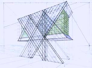
For our 3D sketching example idea we choose to design a Christian Church, to be settled in the valley of México. It is worldwide known that the cross is the most powerful symbol for Christians. There are many churches around the world expressing the cross in many ways, mainly through its architectural plan layout or at the top of the towers and vaults as a sculptural ornament. Thinking about this symbol —during a sermon in Union Church (México)— my very first thought was: why not consider the whole building as a cross? Perhaps a church like this already exists somewhere. I am not claiming here its originality but its origin, as an insight for an architectural idea.
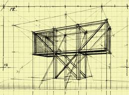
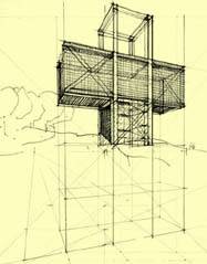
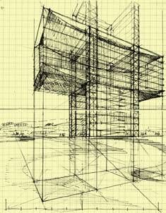
Our first attempt was to visualize the idea formally, as it is showed in Figures 8 and 9. During its execution some questions arouse immediately, such as: What dimensions are we dealing with? What structural system and materials must we think over? What colors would be suitable for the curtain glass windows? Under which criteria should we select the landscape settlement? And so on, many other questions come up. Our second attempt went into the volumetric configuration, discovering more problems to solve. See Figure 10.
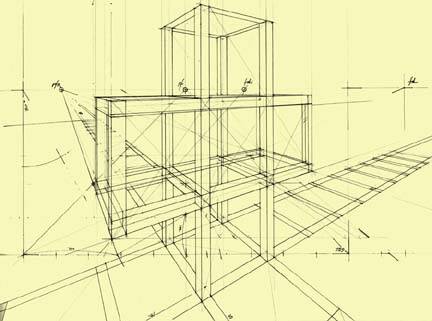
Having these questions in mind, we introduced in our third attempt the architectural layout of proportions in order to rule the composition, as we can see in Figures 11 and 12. Vignola and Palladio were the masters in architectural design through proportions —as well for historical building analysis—, from which we can learn how to apply them even to modern buildings.
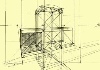
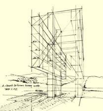
As a result of this 3D sketching process we grasp a code to explore, as Soddu says: “This first design act is the occasion to use the code as a means of possible transformations, and the traced form is a frozen moment of this transformation process. We are not able, in fact, to transform a white sheet: we trace a form transcribing our memory a spark of the idea.” [6] So we decided to explore the x-cross composition as another possible transformation of the original code, being careful to notice when its meaning changes radically, to step back immediately, as it occurred in Figure 13. We realize at this point that a code cannot be broken without changing the idea. A code, as a system of architectural elements, can be transformed over and over until it reaches one of its possible arrangements.
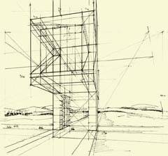
Working on the code our visual thinking starts playing its role in the process, as Arnheim says: “Our thoughts influence what we see, and vice versa.” [7] And that indeed happens. Until we turned the view’s perspective, as it can be appreciated in Figures 14 and 15, we realize that the large lateral walls forming the cross could be capable of holding all the complementary activities of the church, as small independent buildings linked by the sanctuary, in other words, a church between living-walls.
Of course we tried to find out a meaning for the living-walls from the historical point of view. Observing a perspective section of San Peter (Rome, ca. 320-329), the four lateral aisles accomplish an important structural function as well as housing complementary activities. So we thought that the basilical spatial configuration —of two lateral aisles, in this case— could match pretty well for the living-walls without destroying its vertical expression, that of the cross.
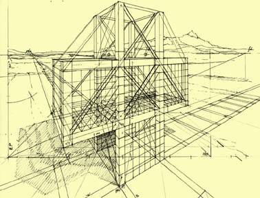
Once the idea-code was reached a feedback process begins reformulating our original inquiries, but this time giving them architectural answers. That is the case of Figure 16 in which we feedback Figure 12, improving its architectural elements. After this final attempt we find ourselves ready to develop the architectural drawings; plans, elevations, sections and details mainly. The quality of this process depends upon our professional training and capacity as well as the teams we work with —for structural calculus, contractors and so on. At this point there is no more idea to grasp or a code to transform but the building process alone.
I would like to close this writing going back to the concept of idea in generative design. At least in architecture, an idea is always three-dimensional, or better said, fragmentary-three-dimensional. Soddu gives us a great example recreating the possible requests made to Borromini for Sant’Agnese: “I imagine the request made to Borromini for the church of Sant’Agnese in Piazza Navona: I want the church be present in the whole square, inside the square but, at the same time at the limit of it; the dome has to be present in all the square, it has to move itself amplifying the character of the square that is a lengthened elliptic Roman passage.” [8] As we can notice all verbal-requests evoke 3D images otherwise it would be as tedious and useless to translate it into 2D “ideas.”
When Renzo Piano decided to build in stone the new cathedral for Padre Pio, in San Giovanni Rotondo (Italy), he took the arc as its code through which a 360º view from the interior was generated in response to the infinite landscape. His code rested upon the stone and the technology to carve stones in different sizes using a computer program —because the arcs, all of them, have different spans too— as if they were standardized production. This is one of the many ways in which computers become a designer’s friend. Borromini’s idea was probably to connect in harmony its church with the surrounding space. Renzo’s idea matches in his own words: “Architecture is always the construction of emotions through technical means.” Our church’s idea suggests that architectural forms can be conceived and transformed within its natural dimensions.
References
and Notes
[1] Tomás García-Salgado, “Distance to the Perspective Plane.” Nexus Network Journal (out coming issue on perspective and optics), vol. 5, 2003, at nexusjournal.com
[2] perspectivegeometry.com (This Web Site is directed by Tomás García-Salgado)
[3] Celestino Soddu, "From Forming to Transforming" (paper at GA 2000 Conference, Milan 2000) generativeart.com
[4] Charles Van Doren, A History of Knowledge (USA: Ballantine Books, 1992) p. 381.
[5] Edward Burton, “Artificial Innocence: Interactions between the Study of Children’s Drawing and Artificial Intelligence”, Leonardo, Vol. 30 No. 4, pp. 301-309, 1997.
[6] Soddu [3]
[7] Rudolf Arnheim, Visual Thinking (USA: Univ. of California Press, 1969), p. 15.
[8] Soddu [3]
[9] All perspective drawings were rendered using the Modular Salgado Scale (RMS).
![]()
More information at perspectivegeometry.com (comments).