From design to production:
Three complex structures materialised in wood
Abstract
This paper explains some concepts used by the designtoproduction group at the Chair of CAAD to materialise complex form by example of three recent projects that were realised in collaboration with different partners: First, a platform for the exhibition “Inventioneering Architecture” in San Francisco, where a NURBS-surface was translated into the geometry for 1000 individually shaped rafters forming a doubly curved surface of 120 square metres. Second, the realisation of a sculpture designed by Daniel Libeskind for the University of St. Gallen where the “algorithmic” form was taken as a basis for organising and rationalising the construction and manufacturing process for over 2200 different parts. And third, the design and realisation of a spherical pavilion for the SWISSBAU-fair in Basle composed of some 300 different quadrilateral frames, whose geometries were generated and optimised by means of artificial life methods. All three works were manufactured on a computerised five-axis-router.
1. Introduction
In contemporary architecture a strong current is observable towards organic, non-orthogonal, free and complex form. Both, planners as well as their clients strive to extend the possibilities of architectural geometries. The designers on one side are heavily supported by ever more powerful 3D CAD-modellers to help with form finding and are eager to use this potential. On the other side computerized (CNC) fabrication technologies enable the creation of individually parameterized parts for almost the cost of a standardized mass product. But in between those two sides often insurmountable challenges arise when it comes to detailing: Since free forms consist of a large number of individual components the planning effort scales with the number of parts, often not even linearly. The amount of border conditions to fulfil and plans to draw is in many cases out of the ordinary planning process. Sometimes this is avoided by creating “quasi-free” forms from a limited number of repetitively used components whose regularity is not visible at first sight, like in the Beijing Swimming Stadium by PTW Architects [1,3] or in the Melbourne Federation Square Atrium by Lab Architecture [5]. This rationalisation reduces the realization costs as well as the error rate in fabrication but is not always satisfying the intentions of the designers.
By introducing a continuously digital chain
from form finding to fabrication, the designtoproduction group at the Chair for
Computer Aided Architectural Design (CAAD) at the ETH Zurich seeks to
rationalise not only the structure itself but also the process that leads to
the materialisation of this structure. This ranges from innovative approaches
to generate irregular structures that adapt to external preconditions by using
methods from the field of artificial life [8] until the automatic generation of the code that directly controls
CNC manufacturing equipment. We will illustrate this approach in the three
following case studies that were all realised in the year 2005. By example of
those cases we define a process in six steps from design to production in the
second section of this paper.
1.1 Doubly curved: Exhibition platform for “Inventioneering Architecture”
Doubly curved surfaces pose especially tricky problems to manufacturing. Usually they are either accomplished by approximating the continuously curved surface with a polygonal structure (e.g. the roof structure for the Milan Fair by Fuksas [6]) or by assembling deformed sheet material on a supporting structure (e.g. the BMW Pavilion by Franken [2,4]). When Instant Architects designed the stage for “Inventioneering Architecture”, they first thought of a third principle: milling the doubly curved terrain of the 120 square metre platform out of foam material and coating it with plastic. But it turned out that production costs would be well over the top of the available budget.
„Inventioneering Architecture“ is a travelling exhibition of the four Swiss architecture schools (Zurich, Lausanne, Geneva and Mendrisio) that was first shown at the California College for Arts and Crafts (CCAC) in San Francisco and is now touring the world. For this project the office Instant Architects in Zurich designed a stage, which resembles an abstract crosscut through Swiss topography. This doubly curved platform measures 40 by 3 metres with varying heights up to 1.5 metres. A footpath meanders along the surface, passing the exhibits (Fig. 1).
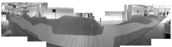
Fig 1: The 40m long exhibition platform at the CCAC in San Francisco after assembly
In order to meet the budget requirements, we proposed to assemble the hilly platform from 1000 individually curved rafters that were milled out of 40mm medium density fibreboard (MDF). They are assembled in comb-shape, so that their overlapping sections form the closed surface of the path while the exhibition area is marked by gaps. By choosing a rather cheap material and implementing a continuous digital chain from the definition of the surface geometry in the CAD software Maya until the control of the five-axis CNC-mill that the parts are manufactured with, production costs could be lowered significantly.
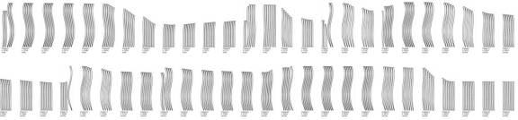
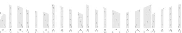
Fig 2: part of the 1100 individually curved rafters optimally positioned on MDF-boards
The detailing was developed closely after the capabilities of a five-axis router. The platform is divided into 40 millimetre wide cross sections, each describing the upper surface path of one rafter. The milling tool follows this path and rotates around it at the same time, cutting out a so called “ruled surface” that follows the topography of the platform both along and across the section. Thus it is possible to manufacture a three-dimensional, doubly curved surface from two-dimensional sheet material at very low cost. The rafters are connected by dowels and supported by perpendicular boards.
Since the structure consists of roughly 1100 individually shaped parts (Fig. 2), the crucial point was to automate the translation of the platform geometry into the geometry of the single parts and finally into the steering code for the computer controlled mill. This was accomplished by a set of scripts in the CAD-package Vectorworks. The first script imports the original design defined as a NURBS-surface in the modelling software Maya, reads the coordinates of the platform’s cross-sections for every rafter and determines the angles of bank. A second script translates this information into the milling paths for all 1000 rafters, also including all drillings for the dowels. A third script arranges and optimises the rafters on the MDF-boards and generates the so called G-Code, the programs which control the five-axis CNC-router. 120 MDF-boards sized 1.0 by 4.2 metres were used to fabricate all rafters within roughly 50 milling hours.
1.2 Complex puzzle: Libeskind’s Futuropolis Sculpture
The second project to be introduced here is substantially more complex than the Inventioneering Architecture platform. First, the structure consists of twice as many individual parts – summing up to 2200 in the end. Second - and more important - the geometry was not defined explicitly as a NURBS-surface but implicitly in the form of geometric production rules. The digital chain thus had to start one step earlier, by generating the geometry of the structure.
“Futuropolis” is a wooden sculpture designed by New York architect Daniel Libeskind for a workshop he held at the University of St. Gallen (HSG) in October 2005 (Fig. 5). HSG, a renowned business school, introduces its new students with a freshman week every year. In 2005 the aim of the 5-day workshop was to conceptualize a “City of the future” and visualize the ideas by help of the complex formed towers of the Futuropolis sculpture.
The design is based on a triangular grid, where a 98 tightly packed towers form an ascending volume of up to 3.8 metres height. The towers are built from roughly 600 wooden boards that are intersecting the sculpture at an angle of 25 degrees and show the same pattern as the footprints of the towers. Thus, the boards are

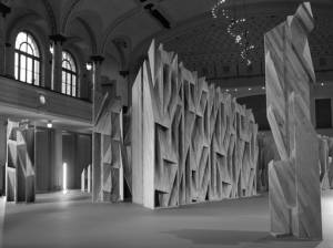
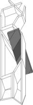

Fig 3: constructive principle: one
board intersects several towers
Fig 4: the detailed and structurally
optimised sculpture
Fig 5: Libeskind’s Futuropolis at the
concert hall St. Gallen
cut into almost 2000 wooden polygons by the perpendicular faces of the towers (Fig 3). To realise this design within the given time and budget was not possible by means of traditional craftsmanship, so again a complete digital production chain was set up.
The first challenge was to find an appropriate construction method to connect the boards of each tower so that maximum structural integrity could be guaranteed at minimum production and assembly costs. By using aluminium dovetail-connectors, the number of connection details could be reduced to only six variants with eleven subtypes, whose mitres and notches can be milled by a CNC-router.
The second challenge was to generate the exact geometry of all 2164 parts, including the bases where the towers stand on. A completely parameterised CAD-model of the sculpture was programmed in Vectorworks, which calculated the outline of all parts by closely following the algorithmic design rules given by the architect (Fig. 4). The appropriate connection details where automatically assigned to the edges, the parts were numbered and arranged on boards (Fig. 6).
 The third step was to translate this geometry information into the
steering code for the CNC-machine. Since the boards had to be turned around in
the middle of the production process, two G-Code programs per board had to be
generated by a script. Also the exact widths and lengths for calculating the
material costs and for preparing the raw boards were automatically exported as
data-tables. The sculpture consists of 360 square metres of 32 mm thick boards,
altogether almost 11.5 cubic metres of birch wood. Total milling time summed up
to about 200 hours, the assembly took roughly 500 man-hours.
The third step was to translate this geometry information into the
steering code for the CNC-machine. Since the boards had to be turned around in
the middle of the production process, two G-Code programs per board had to be
generated by a script. Also the exact widths and lengths for calculating the
material costs and for preparing the raw boards were automatically exported as
data-tables. The sculpture consists of 360 square metres of 32 mm thick boards,
altogether almost 11.5 cubic metres of birch wood. Total milling time summed up
to about 200 hours, the assembly took roughly 500 man-hours.
Fig 6: Futuropolis consists of 628 boards, each containing parts of various towers
1.3 Organically optimised: The CAAD Swissbau Pavilion
Like in the second example, the digital chain in this case started with the generation of an explicit geometry from an implicit set of rules. But instead of having „geometrical rules“ that deterministically defined the final geometry like in the Futuropolis project, this time „functional rules“ were used to generate a unique optimised geometry for a given environment by help of a self-organising process [7].
The CAAD Swissbau Pavilion was designed and built to show the potential of the digital chain on the Swissbau 2005 fair in Basel (Fig.8). It has the form of a sphere with two metres radius and reaches a height of three metres. It is assembled from quadrilateral wooden frames, each consisting of four wooden boards standing perpendicular on the surface of the sphere. But while in a traditional coffered dome a regular structure dictates the placement of openings, here the frames are required to adapt their size and angles to the deliberately asymmetric placement of windows.
To generate this adaptive geometry, an interactive software was programmed in Java that simulates the growth of a quadrilateral mesh on a sphere following simple rules: The edges try to align with the positions of the predefined openings and the floor level, while at the same time every mesh attempts to optimise its size and angles. The simulation of this process is running in real-time and can be influenced directly by the user. Under certain circumstances the structure can locally alter its topology by inserting or deleting meshes until it reaches a stable state (Fig. 7). The resulting geometry of nodes and edges is then exported to an XML file and used as the base for the rest of the digital chain.
The subsequent steps are analogue to the first two examples: a script reads the XML file into the CAD-software Vectorworks and generates a 3D-model of the pavilion with the exact geometries of all 320 wooden frames and their 1280 parts. All parts are automatically numbered and a second script arranges them on the raw boards used for milling. The G-Code for controlling the CNC-router is exported automatically for every board and already includes information for drilling the holes and milling the unique part-id into the boards.
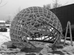
Fig. 7a-c:
Starting configuration and growing mesh
Fig. 8 Materialising a simulation: the assembled pavilion
2. The designtoproduction-process
From the experiences gained in the described examples we define a process, which leads from the design to the production of complex structures in six steps. It starts right after the design and it ends just before production, tightly filling the gap between the designer and the manufacturer, negotiating their respective requirements and building a sustainable connection. The aim is to implement a “digital process chain” that contains all necessary information in one (or more) parameterised digital model(s) and allows for CNC manufacturing of many individual parts without having to manually design every variant.
2.1 Definition of geometric, functional and constructive requirements
It all starts with design-input. The first step in the process is to carefully identify the requirements of shape, function and construction together with the designers. Depending on the type of project the focus may be shifted between those three topics. In our examples, the Futuropolis project was dominated by the very detailed description of the geometric principle whereas in the other two examples only the overall shape was given and the geometry of the single parts could be modified. The Swissbau Pavilion especially illustrates this by self-organizing its components around the given openings (function) and optimising the size of the meshes (construction). For the Inventioneering Architecture platform the overall geometry was predefined and functional requirements were given by the footpath across the structure and the need for easy assembly and shipping in a standard overseas container but there were no prerequisites at all for the construction method. This stage defines the “playground” for finding a solution.
2.2 Definition of materials and constructive details
Going on from the definition of requirements, the next step is to identify adequate materials and construction methods. Already at this stage the “other end” of the process, the production, kicks in. External manufacturing specialists – in all our examples carpenters with a high degree of experience on CNC-tools – are integrated in this early phase in order to find optimum solutions for all questions of material and constructive detailing. This is especially necessary to identify points in the production chain, where material properties can be exploited and cost intensive manual labour can be avoided. For example the dovetail-connectors used in the Futuropolis and Swissbau project made it unnecessary to clamp the freshly glued parts for drying and thus saved an immense amount of work. Another important issue within this phase is to reduce the number of different details. In the Futuropolis sculpture there are 15 different variants of two to eight boards meeting at one point. After optimisation it was possible to build all those connection alternatives from only six different types of board-cuts. In the Swissbau-Pavilion there is only one single parameterised connection detail: a mitred cut with a notch for the dovetail. The mitre-angle of course changes from part to part and is essentially never the same.
2.3 Definition of the structure’s geometry: start of the digital chain
Up to now the process resembles very much the usual way of gradually bringing a design to the building stage. In the third step however this is fundamentally changed by introducing the first link of the digital chain that will connect the design directly to the production. After the constructive details are fixed, the next step is to exactly describe the structure’s geometry. For highly complex structures there are three different ways to do so:
Explicit definition by design
In this case, the geometry is already entirely defined (digital) model of the shape. In the Inventioneering Architecture project for example, the form of the stage was designed by creating a NURBS-surface with the modelling software Maya. The landscape was explicitly shaped until it fitted the requirements of the designer and then cut into sections. The built result matched this geometry exactly, because the coordinates and curvatures of all the rafters could be directly read from the NURBS surface.
Implicit definition by concept
A more abstract way of defining the geometry is to give a description of the concept how it is derived. In the Futuropolis project the shape was not explicitly defined (although a three-dimensional CAD model existed) but was given as a set of geometrical production rules: “Take this shape, extrude it vertically, intersect it with an inclined plane, extrude the intersection perpendicular to the plane…” and so on. From this algorithmic description an actual algorithm was programmed that could generate the exact geometric description for all 2200 parts in a few seconds. Something that would have taken weeks if attempted manually and had to be repeated after every minor change of the design.
Generation by optimisation
The most sophisticated form of defining the geometry was implemented for the Swissbau project. Instead of a deterministic algorithm that ends with the same outcome every time like in the Futuropolis sculpture, a non-deterministic approach was used, that optimises the geometry by using a dynamic simulation system. Depending on the parameter setting at the beginning and the user interactions, the system ends up in a different state every time it is run. But it still produces a result matching the predefined requirements every time.
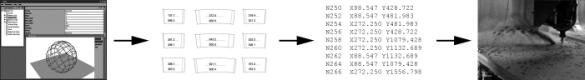
Fig.
9a-d: The major steps of the designtoproduction-process
a.
Definition of the structure’s geometry, start of the digital chain (2.3)
b.
Generation of geometry for every single part and optimisation (2.4, 2.5)
c.
Generation of production code (G-code) (2.5)
d. Production on a CNC-machine
2.4 Generation of geometry for every single part
After defining or generating the exact geometry of the structure with one of the above methods, this “abstract” description has to be translated into detailed geometries for the single parts. The optimisation program for the Swissbau pavilion for example returned only the coordinates and edge-relations of the generated mesh. The actual geometries of the boards forming the quadrilateral frames were then generated and numbered automatically upon this information by a different CAD-script. In the Futuropolis project, the cutting angles and connector-geometries were added to the board outlines in this phase. Thorough quality control is done at this stage because systematic errors in the previous steps are likely to become visible here. If possible, 1:1 prototypes of selected components are produced to identify problems. Also the net material demand can be calculated.
2.5 Optimisation for production
In the next step the parts are optimised for production, usually by arranging a multitude of parts on a board of raw material so that the waste is minimized. Also additional details for production are added, for example holes for fixing the boards on the table of the router machine. In the Swissbau pavilion this holes were later also used to connect adjacent frames by bolts, so they had to be placed exactly in order to match. On the manufacturing side, the material can now be prepared e.g. by cutting up the raw boards into appropriate chunks. Also arrangements for numbering the single parts – e.g. by sticky notes – and the generation of assembly drawings take place at this stage.
2.6 Generation of production code
The production code (“G-code”) for the CNC-machine is the final result of the digital production chain. G-Code is basically telling the machine which tool to choose and where to move it. Usually, this is programmed by the manufacturer on the basis of detailed construction drawings. For the automated generation of the G-code in our digital process chain, only a single exemplary part of the structure is processed this way and the resulting code is used as a prototype for the other parts. A final script is created which generates the appropriate code for all parts from the optimised CAD-model. Those codes are then handed back to the manufacturer and fed directly into the five-axis-router to start the production.
3. Conclusions
After having realised three different projects we are able to sum up some results that became very clear. Quality, flexibility and efficiency were the main issues in all the projects. The potential of the presented process to resolve those issues actually made it possible to realise the projects, which would have been too complex and cost intensive otherwise.
3.1 Quality
With CNC manufacturing it is possible to achieve a level of exactitude that is not within reach of manual work at this project scale. By implementing a digital chain this quality can be maintained throughout the whole process, which essentially makes it possible to create structures from a few thousand individually shaped parts which fit to the tenth of a millimetre at every contact point. Usually the tolerances of the CNC machines are very reliable and the material tolerances (especially when working with wood) are much more challenging. At the same time the digital process requires an algorithmic approach to quality management with more bug-fixing in software development than measuring of fabrication tolerances. The generation of geometries and fabrication codes by software mostly leads to either entirely correct or entirely flawed results but the flaws are sometimes difficult to detect due to the complexity of the structure. Plausibility checks have to be carefully designed and performed after every step of the process.
3.2 Flexibility
Since the whole process relies on a parameterised digital model, it responds very well to changes. Late design alterations as well as other changes are no problem as long as they lie within the boundaries of the model. In the Futuropolis project for example, it turned out that the delivered material was two millimetres thicker than expected, which changed the geometry for all 2200 parts. The new G-Codes for the CNC-router could be generated practically over night, so the production schedule was not influenced.
3.3 Efficiency
For all three examples, detailed calculations provided by the manufacturer showed how much it would have cost to fabricate the projects on the same CNC-machine but without a digital chain delivering the machine-ready data. In all three cases the figures are impressive: the reduction of manufacturing cost ranges from 72% in the Futuropolis project up to 83% in the Swissbau project. Primary cost factor in the “conventional” CNC-process is the programming of the G-Code and the optimisation for production, which were completely taken off the manufacturer’s shoulders and done much more efficiently by the use of parameterised CAD-models. When considering the expenses for consulting and programming in the six designtoproduction phases, the saving potential is still around 25 to 50 percent of the total budget.
3.4 Future work
All three presented projects were executed in wood by the same fabrication partner on a five-axis router over the last year. We are aware that there are many more CNC machines to work with and an infinite number of different materials. However we think that especially in woodwork there is a huge potential to improve CNC-manufacturing, mainly because of the three-dimensionality of the material as opposed to for example laser cutting of sheet metal. In the nearby future, we would like to transmit our experience from exhibition and interior projects to a building scale. We expect to face three challenges:
Scale – Is it possible to “scale” our working process regarding the size of the parts and their number? How do bigger machines and material dimensions influence the process?
Scope – Is it possible to cover the design and production of a whole building with digital chains or is this method rather suitable for separate parts of a building such as a façade or a roof construction? What are the criteria to decide between manual and digital workflow?
Organisation – So far we have worked with rather linear production chains and just one manufacturing partner, without interfaces to other planners and producers. Can a linear digital chain become a “digital network”, addressing all the planners and companies involved in the building process?
Credits
We would like to thank the following persons and institutions for supporting our work: Bach Heiden AG in Heiden (CH), namely Franz Roman Bach and Hansueli Dumelin who realised all the projects with us. The University of St. Gallen (HSG), namely Timon Beyes, Christoph Michels, Susanne Falk and Holm Keller for organising the Futuropolis Project. The Studio Libeskind in New York, especially Thore Garbers, for designing it. Instant Architects, namely Dirk Hebel, Jörg Stollmann and Sascha Delz in Zurich for their cooperation in the Inventioneering Architecture project. And last but not least Prof. Dr. Ludger Hovestadt, head of the Chair of CAAD at ETH Zurich for supporting and funding.
References
[1] S. Bull, Downing, Steve, Beijing Water Cube - the IT challenge, The Structural Engineer, Vol. 82, 2004, pp. 23-26.
[2] P. Cachola Schmal, Workflow: Architecture - Engineering, Birkhäuser, Basel, 2004.
[3] T. Fischer, Generation of Apparently Irregular Truss Structures, in: B. Martens, A. Brown (Eds.), Computer Aided Architectural Design Futures 2005, Vienna (Austria), 2005, pp. 229-238.
[4] B. Kolarevic, Digital Praxis: From Digital to Material, in: S. Sariyildiz, B. Tuncer (Eds.), Innovation in Architecture, Engineering and Computing (AEC), Vol. 1, Delft University of Technology, Faculty of Architecture, Rotterdam, NL, 2005, pp. 5-18.
[5] Lab-Architecture, Federation Square, Vol. 2004, Lab Architecture, 2001.
[6] J. Sanchez-Alvarez, Materialising Geometry: The Free-Form Reticulated Roof Structures for the New Milan Fair, in: S. Sariyildiz, B. Tuncer (Eds.), Innovation in Architecture, Engineering and Computing (AEC), Vol. 1, Delft University of Technology, Faculty of Architecture, Rotterdam, NL, 2005, pp. 19-32.
[7] F. Scheurer, A Simulation Toolbox For Self-Organisation In Architectural Design, in: S. Sariyildiz, B. Tuncer (Eds.), Innovation in Architecture, Engineering and Computing (AEC), Vol. 2, Delft University of Technology, Faculty of Architecture, Rotterdam, NL, 2005, pp. 533-543.
[8] F. Scheurer, Turning the Design Process Downside-Up - Self-organization in Real-world Architecture, in: B. Martens, A. Brown (Eds.), Computer Aided Architectural Design Futures 2005, Springer, Dordrecht, Vienna, 2005, pp. 269-278.