Virtual
net in a real environment
Acad. Ms. Arq. Silvia
Lenyra Meirelles Campos Titotto
Department of
Design and Architecture, Faculty of Architecture and Town Planning,
University of
São Paulo
e-mail: titotto@gmail.com
Acad. Eng.
Felipe Estrella Barros
Department of
Energy and Automation, Polytechnic School,
University of
São Paulo
e-mail: festrella@uol.com.br
Profa. Dra.
Clice de Toledo Sanjar Mazzilli
Department of
Design and Architecture, Faculty of Architecture and Town Planning,
University of
São Paulo
e-mail: clicemazzilli@terra.com.br
Abstract
This project consists on an
installation of several common laser beans (models of
laser beans that are normally used
on presentations), mirrors and a light sensor (LDR - Light Diode Resistor).
The laser beans are positioned with
their aims focused on the mirrors. Through the
reflection of the mirrors, it is
possible to create virtual obstacles. If a person or an
object crosses the laser, the light
sensor notices the interruption and will trigger an
alarm. A source power will be
developed in order to replace the laser beans'
batteries and the alarm circuit. The
alarm circuit will be also designed for this work.
Working Principle
The conception
of this project is directed to the study of the environment response due to a
human action. Based on that subject, an environment was prepared with several
visible rays of laser. If one of theses rays is interrupt (eg. someone crosses
it), an alarm will be triggered. Therefore, the space of the environment is
sensible to the presence of people.
It can be also
quite interesting to try to dodge the rays, as if it was a virtual barrier or
labyrinth existing in a real space.
Technical Issues
Power
Source
The reason to develop the power source is to replace
the laser beans batteries - which don’t have autonomy greater than a couple
hours - and also to feed the trigger circuit (see circuit diagram on figure 1).
The AC input chosen was 220 V, because it is the
voltage provided in Europe.
There are two different outputs. One output is
stabilized, with DC 5 V and 5 W maximum power. It has the purpose to feed the
laser beans. The 7805 voltage regulator is the one that best suits to the
lasers connections, because it’s voltage output is 5 VDC, while the beans need
4.5 V. The difference of the voltage will be solved through the insertion of a
resistor in series with each bean.
The other output will be used on the alarm circuit. It
is not stabilized and has 12 VDC voltage with 40 W maximum power output.
|
|
|
Figure 1 – Stabilized 5 V power source |
Laser
Beans
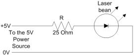
This experiment will have 4 laser beans, fed by the 5
V power source. Each laser bean works with a 4.5 V voltage and 20 mA current. Therefore, using the Ohm’s law,
follows:
|
|
(1) |
The resistor R calculated in (1) will be set in series
with each laser bean, as represented on figure 2.
|
|
|
Figure 2 – Connection of the beans to the Power
Source |
Alarm
Circuit
The alarm circuit consists on a LDR sensor (Light
Diode Resistor) that operates as a trigger of the BC327 transistor. If the ray
of laser stops falling upon the LDR (eg. a person or an object has crossed the
laser ray), it will make the transistor enter on its conducting procedure. If
the transistor starts conducting, it will energize the relay. The relay has an
electric seal that keeps it energized even if the transistor stops conducting.
The siren is connected through the relay to the 12V power source, therefore, if
the relay is activated, the alarm is triggered.
The only way to reset the alarm is to push the
pushbutton break.
The alarm circuit’s sensibility is adjusted by the
potenciometer.
The circuit diagram is shown on figure 3.
|
|
|
Figure 3 – Alarm circuit diagram |
Mirrors
and support
The project will have 13 mirrors, with dimensions of
50x50 mm and transparency equal or greater than 70%. They will be attached on
55x55x20 mm cubical pieces of wood.
A hole of 6mm2 will transpose the lateral
of the wood, in parallel with its surface. Through this hole, it will be stick
a piece of cable, very hard and with thickness of 6 mm2. Glue can be
used in order to fixate the wire inside the hole.
The support can also be made of wood. A rectangular
base of heavy wood (about 5 kilos) should be enough. A vertical wood stick made
of brown stick can be settled trough a hole on the base.
The mirrors will be placed on the vertical stick
through 6 mm2 horizontal perpendicular holes, which will receive the
wire from de mirrors.
The mirrors adjusts will be made by deforming and
twisting their wire. The laser beans and the LDR sensor can also be attached
through this 6 mm2 wire to the bases.
Another possibility to fixate the lasers and the
mirrors is to attach the devices on common professional microphones stabling
systems (see figure 6 ).
Room
environment
It is imperative to prepare the room for almost
complete darkness, otherwise the lasers won’t be seen. To provide a carrier in
the air that helps to make the rays of laser more visible, a glycerin smoke
machine can be used.
The Results
This installation was simulated in a CAD system, and
some angles of it were rendered in order to demonstrate the environment. On
figure 4, there is an isometric view of the installation, made on a square
space.
|
|
|
Figure 4 – Isometric view of the installation |
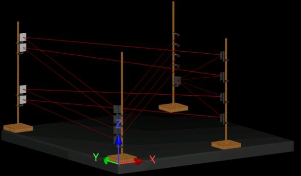
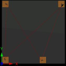
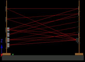
Figure 5 shows the top and side views of the
installation.
|
|
|
|
Figure 5 – Top view (on the left); side view (on the
right) |
|
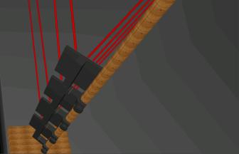
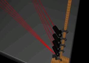
The mirrors and lasers were sketched with an attaching
system based on microphone stabling devices.
|
|
|
|
Figure 6 – Four mirrors set on a wood base (on the
left); Four laser beans and a mirrors set on a wood base (on the right) |
|